Fuel cell system, fuel cell operation method, and gas treatment device

Inactive Publication Date: 2006-07-27
NEC CORP
View PDF3 Cites 0 Cited by
  • Summary
  • Abstract
  • Description
  • Claims
  • Application Information

AI Technical Summary

Benefits of technology

[0019] In such a configuration, it is possible to oxidize the gas introduced from the container into the exhaust gas passage more efficiently and reliably. In addition, it is possible to completely oxidize and remove the components efficiently and more reliably and retain its original performance, even if the components not completely oxidized by the catalyst and liquefied components deposit on the catalyst after operation of the fuel cell system for an extended period of time. Thus, it is possible to improve the maintainability and reliability of the fuel cell system additionally.
[0020] The fuel cell system according to the present invention may have a unit accelerating discharge of the gas present in the outlet passage additionally. In this manner, it is possible to oxidize and then discharge the gas present in the outlet passage into the air efficiently.
[0021] The fuel cell system according to the present invention may have multiple fuel cells, and a container may be installed in contact with the fuel electrode of each of the multiple fuel cells. In this manner, it is possible to have a configuration containing a catalyst onl

Problems solved by technology

However, in the conventional fuel cells, the unreacted fuel and the by-products discharged from the fuel cell were collected in the container, and the container after the collection is processed as it is separated from the fuel cell, and thus, such a system had a problem that the container after the collection demands tedious processing for waste disposal or recycling.
Such a fuel cell

Method used


Image

  • Fuel cell system, fuel cell operation method, and gas treatment device
  • Fuel cell system, fuel cell operation method, and gas treatment device
  • Fuel cell system, fuel cell operation method, and gas treatment device

Examples


first embodiment

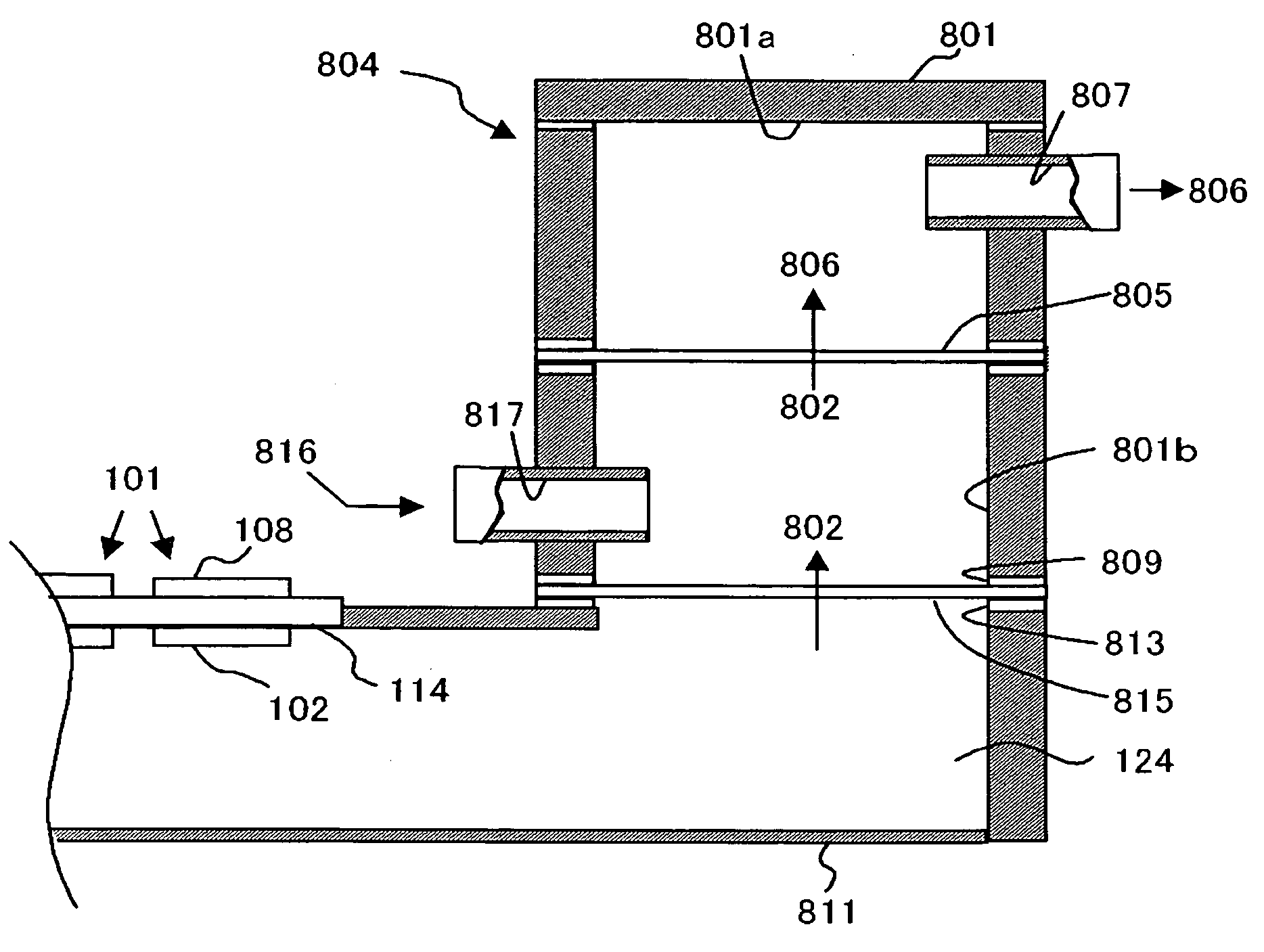
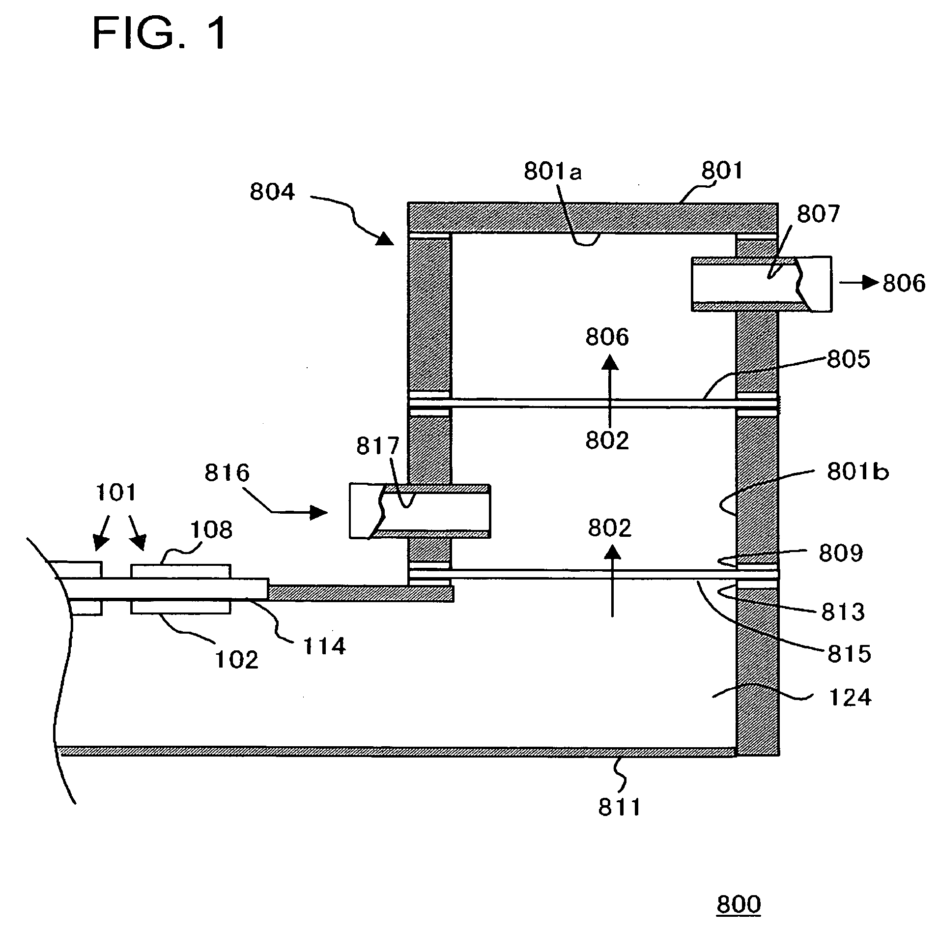
[0044]FIG. 1 is a schematic sectional view illustrating the structure of a fuel cell system in an embodiment of the present invention.

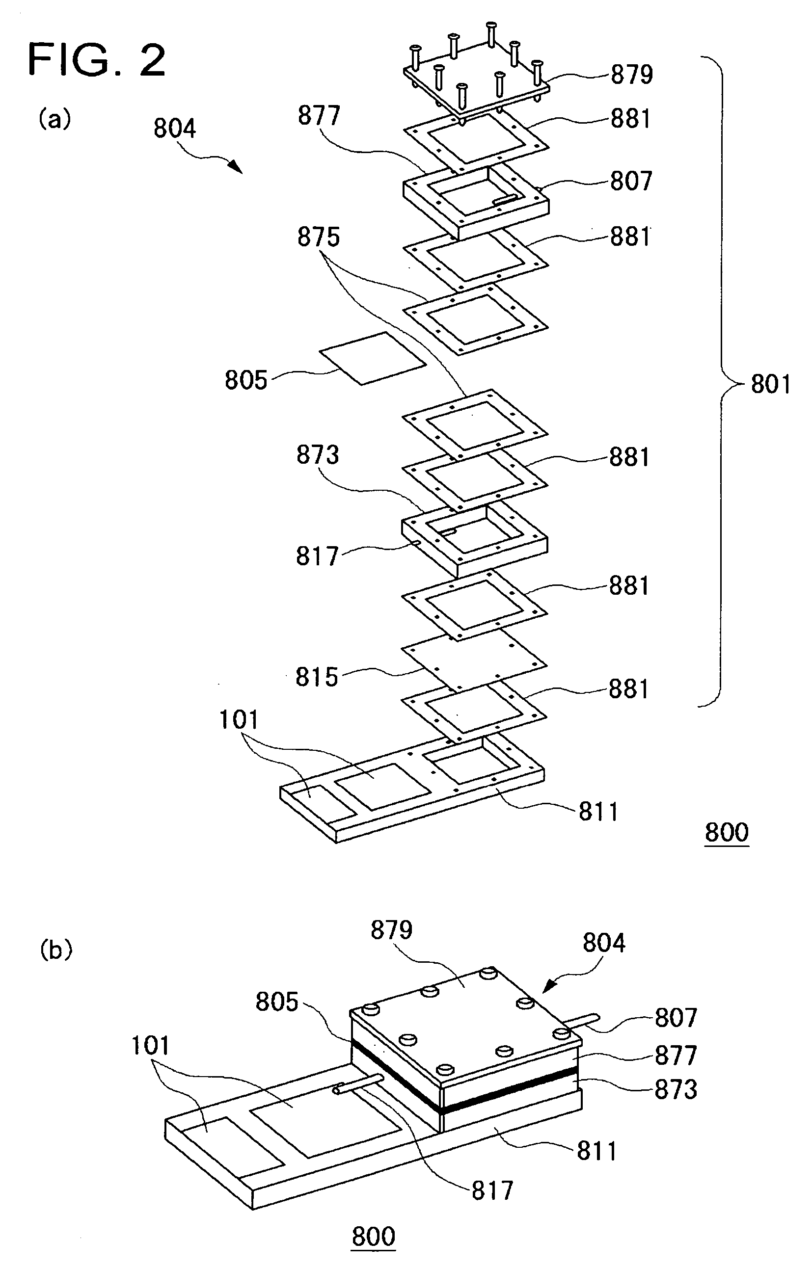
[0045] The fuel cell system 800 includes a plurality of unit cells 101 of a fuel cell and a gas treatment unit 804 treating the gas discharged from these unit cells 101.

[0046] Each of the unit cells 101 includes a fuel electrode 102 and an oxidant electrode 108 as well as a solid electrolyte membrane 114 placed between them, and a fuel 124 is supplied to the fuel electrode 102 and an oxidant to the oxidant electrode 108, generating electricity in an electrochemical reaction. The unit cell 101 is a direct type fuel cell in which a liquid fuel is supplied to the fuel electrode 102. For example of the fuel 124 may include organic liquid fuels such as methanol, ethanol, dimethyl ether, other alcohol, or liquid hydrocarbon such as cycloparaffin or the like. The organic liquid fuel may be an aqueous solution. Normally, air is used as the oxidant, but an o...

second embodiment

[0064]FIG. 3 is a schematic sectional view illustrating a structure of a fuel cell system in an embodiment of the present invention.

[0065] The fuel cell system 820 in the present embodiment is different from the fuel cell system 800 in the embodiment above, in that a gas treatment unit 824 is formed to each unit cell 101 of the fuel cell.

[0066] In the system, the gas treatment unit 824 is formed in the upper region of the unit cell 101. The unit cell 101 is placed close to an opening 813 of the fuel container 811, and a gas-liquid separation membrane 815 is placed over a hole 823 formed in the solid electrolyte membrane 114 of the unit cell 101. In such a configuration, it is not necessary to make a region for the gas treatment unit 824 available, separately from the region for the unit cell 101, and to make the fuel cell system compact and reduce the size of the entire system.

third embodiment

[0067]FIG. 4 is a schematic sectional view illustrating a structure of a fuel cell system in an embodiment of the present invention.

[0068] The fuel cell system 830 in the present embodiment is different from those in the first and second embodiments in its shape of the catalyst. The fuel cell system 830 contains a catalyst 835 in the shape of wire wool. The catalyst 835 is filled in the exhaust vent 807 placed at the top of an outlet passage 831.

[0069] In the present embodiment, the wire wool-shaped catalyst 835 may be made of a metal, an alloy, or the oxide thereof similar to that contained in the catalyst layer 805 described in the first embodiment.

[0070] Although not shown in the Figure, the outlet passage 831 may have a configuration having an oxygen inlet 817 for supplying the oxygen 816, similarly to those described with reference to FIGS. 1 and 3 in the first and second embodiments; and oxygen 816 may be supplied from an oxygen-supplying unit not shown in the Figure.

[0071...


PUM


Abstract

A fuel cell system (800), including a plurality of unit cells (101), a container (801) having an inlet (809) introducing the gases such as carbon dioxide generated in the electrode reaction by these unit cells (101) and an exhaust vent (807) discharging the gases, and a catalyst layer (805) placed in the container (801) that oxidizes the gases introduced in the container (801), wherein the treated gas (806) after oxidation by the catalyst layer (805) is discharged through the exhaust vent (807) of the container (801).

Description

TECHNICAL FIELD [0001] The present invention relates to a fuel cell system, a method of operating a fuel cell, and a gas treatment apparatus. BACKGROUND ART [0002] A fuel cell, which consists of a pair of fuel electrode and oxidant electrode, and an electrolyte placed between them, generates electricity in the electrochemical reaction occurring when a fuel is supplied to the fuel electrode and an oxidant to the oxidant electrode. Generally, hydrogen is used as the fuel, but recently, a direct type fuel cell, which directly uses methanol, a fuel cheaper and easier in handling, as the fuel, is eagerly studied recently. [0003] When hydrogen is used as the fuel, the reaction on the fuel electrode is represented by the following Formula (1): 3H2→6H++6e−  (1)[0004] When methanol is used as the fuel, the reaction on the fuel electrode is represented by the following Formula (2): CH3OH+H2O→6H++CO2+6e−  (2)[0005] In either case, the reaction on the oxidant electrode is represented by the fol...

Claims


Application Information

Patent Timeline
IPC IPC(8): H01M8/04H01M8/10B01J8/02H01M8/06H01M8/24
CPCH01M8/0662H01M8/24Y02E60/50H01M8/242
Inventor AKIYAMA, EIJIMANAKO, TAKASHIKIMURA, HIDEKAZUYOSHITAKE, TSUTOMUKUBO, YOSHIMI
Owner NEC CORP
Why Eureka
Try Eureka