Stent assembly and device for application thereof

Inactive Publication Date: 2006-07-27
LARSSON ROLF +1
View PDF5 Cites 33 Cited by
  • Summary
  • Abstract
  • Description
  • Claims
  • Application Information

AI Technical Summary

Benefits of technology

[0013] Also, it should allow a stent to be applied or introduced by a simple and quick method. Thus, in a further aspect there is-

Problems solved by technology

This is a time consuming procedure that often may require using a microscope and is rendered complicated by limited accessibility to the site of surgery in the body.
There ar

Method used


Image

  • Stent assembly and device for application thereof
  • Stent assembly and device for application thereof
  • Stent assembly and device for application thereof

Examples


Example

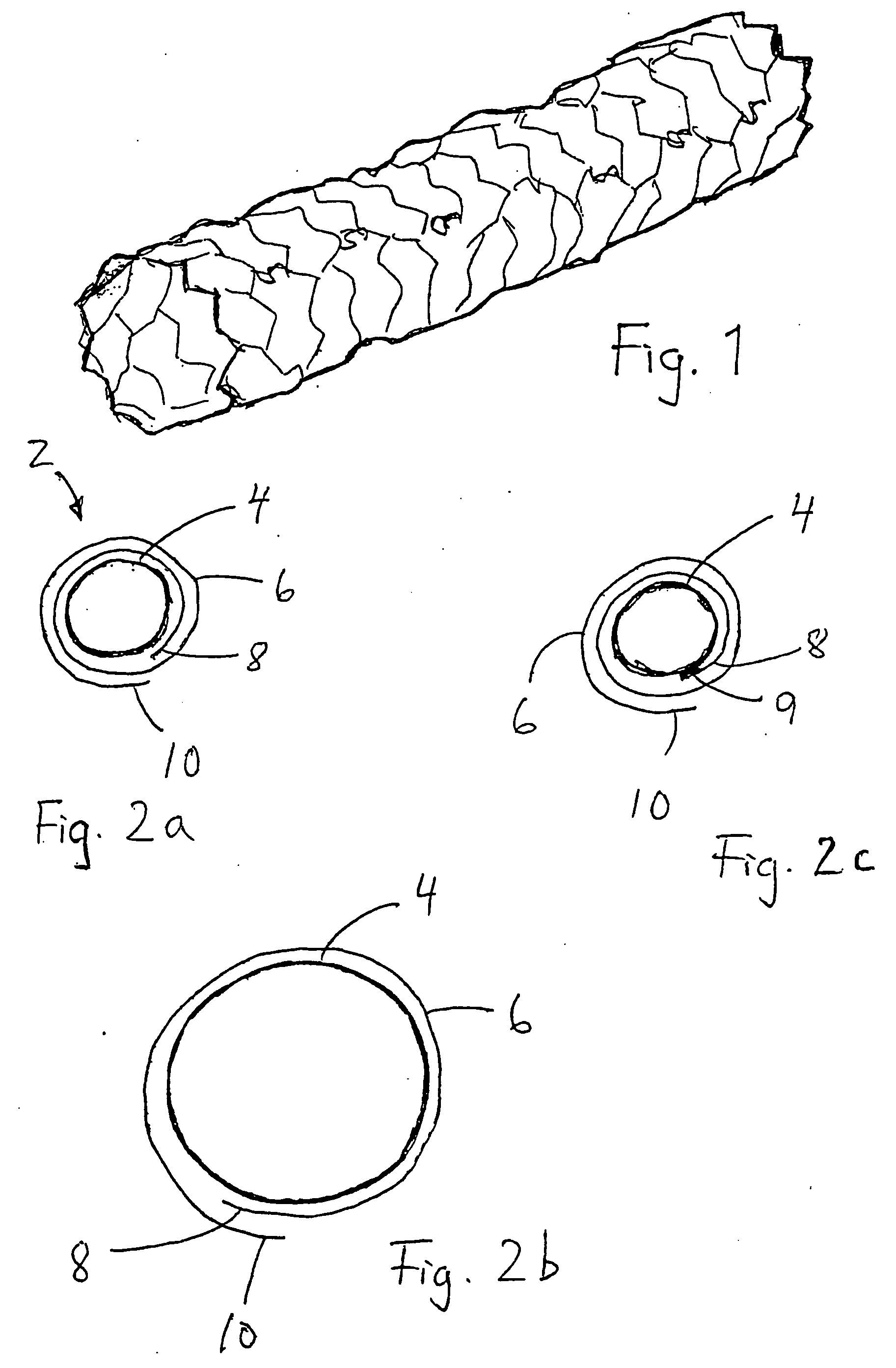
[0026] Stents for anastomosis are supplied in numerous designs, and FIG. 1 illustrates one type of stent suitable for use in the present invention. It comprises a tubular member made from expandable shape memory metal. An example of a suitable material is NiTinol™, which has the capability to regain a given shape when exposed to a given temperature. For the purposes of the present invention, it should be capable of assuming a desired shape when exposed to body temperature, e.g. about 37° C.

[0027] Stents of this type are commercially available, e.g. under the trade name SelfX from Jomed A B, Helsingborg, Sweden. Thus, the actual specific design of the stent member as such does not form part of the present invention.

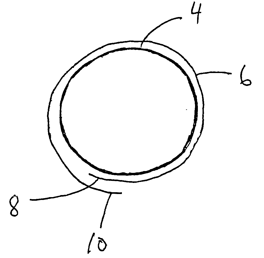
[0028]FIG. 2a-c illustrate embodiments of the basic idea behind the invention.

[0029] A problem often encountered in anastomosis is that the finished joint is very difficult to make absolutely leak-proof under the physiological conditions of pressure prevailing in blood ...


PUM


Abstract

A stent assembly (2) includes a stent capable of assuming a contracted and an expanded configuration. A membrane of a biocompatible material impermeable to molecular transport across the membrane is wrapped around the stent more than one full turn. There is also disclosed a device for performing anastomosis, including a stent assembly (2) in a contracted state and a holding and gripping device (12). The handle has a handle portion (14) and a support structure (16, 18) for accommodating the stent assembly. There is a locking loop (20) that can be tightened around the stent assembly when it is positioned on the support structure, and released to allow the stent assembly to expand to a nominal size.

Description

[0001] The present invention relates generally to devices and methods for connecting severed vessels, e.g. arteries and veins, and in particular to a covered stent and a method and system for applying the covered stent. BACKGROUND OF THE INVENTION [0002] Currently employed techniques for connecting blood vessels in the context of transplantation surgery and other similar kinds of surgical procedures are based on suturing the ends of the vessel with a continuous suture. This is a time consuming procedure that often may require using a microscope and is rendered complicated by limited accessibility to the site of surgery in the body. There are suggestions in the patent literature for facilitating and simplifying this procedure, but they nevertheless suffer from lack of ability to meet some essential requirements. Namely, the method should [0003] be easy to perform in a short time [0004] provide immediate and efficient sealing under physiological pressure and temperature conditions [00...

Claims


Application Information

Patent Timeline
IPC IPC(8): A61F2/84A61F2/92A61F2/00A61F2/06A61F2/07A61F2/90A61L31/16
CPCA61F2/064A61F2/07A61F2250/0067A61L31/16A61L2300/416A61F2/90A61F2002/075
Inventor LARSSON, ROLFGROTH, CARL-GUSTAF
Owner LARSSON ROLF
Why Eureka
Try Eureka