
Methods and apparatus for treating wastewater employing a high rate clarifier and a membrane

a technology of high-rate clarifier and wastewater treatment, which is applied in the direction of membranes, multi-stage water/sewage treatment, liquid displacement, etc., can solve the problems of not being able to disclose the use of a membrane or a high-rate clarifier in the packaged system, and not being able to reduce the load of solids to the membrane, etc., to achieve the effect of reducing or overcoming

Inactive Publication Date: 2006-08-03
ALFA LAVAL ASHBROOK SIMON HARTELY INC
View PDF37 Cites 27 Cited by
  • Summary
  • Abstract
  • Description
  • Claims
  • Application Information

AI Technical Summary

Benefits of technology

[0013] The apparatus and methods of the present inventio

Problems solved by technology

While the patents do describe use of a membrane, there is no provision made for reducing the load of solids to the membrane, and no description of a high rate clarifier.
Moreover, the patent does not describe a packaged system including a high rate clarifier.
None of these patents discloses the use of a membrane or high rate clarifier.
Microfiltration and ultrafiltration suffer from the serious drawback that the membrane tends to foul over time in service.
Deposition fouling occurs as a result of hydrodynamic forces.

Method used


Image

  • Methods and apparatus for treating wastewater employing a high rate clarifier and a membrane
  • Methods and apparatus for treating wastewater employing a high rate clarifier and a membrane
  • Methods and apparatus for treating wastewater employing a high rate clarifier and a membrane

Examples


Embodiment Construction

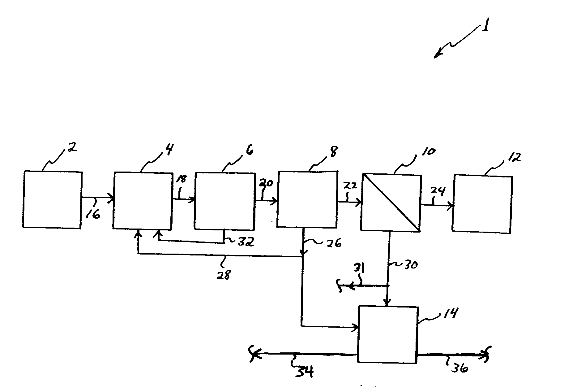
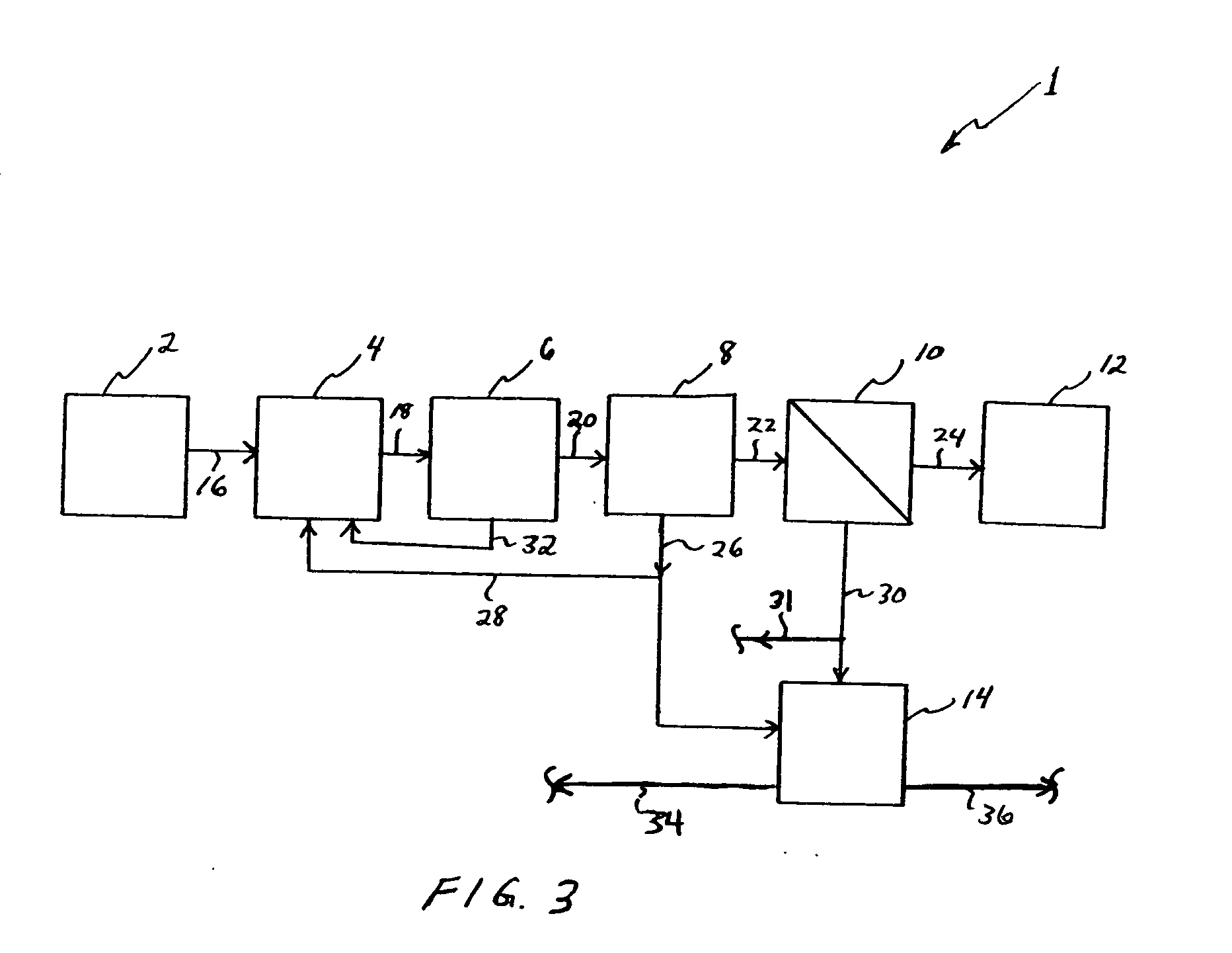
[0027]FIG. 3 illustrates schematically a process of the invention. Embodiment 1 includes a source 2 of screened, raw wastewater, an aerated anoxic stage 4, an aeration stage, 6, a high rate clarifier, 8, and a membrane stage 10. Rather than completely replacing a clarifier with a membrane stage, the inventor herein has conceived methods and apparatus utilizing a combination of a high rate clarifier and a membrane stage. Stream 24 designates a treated effluent routed to storage or its final destination, designated as box 12, while box 14 represents a waste activated sludge (WAS) holding tank, or an aerobic digester, or an anaerobic digester. The various components of embodiment 1 illustrated in FIG. 3 are indicated schematically as being connected via conduits, although as will be described herein, the actual inventive apparatus employed to carry out the inventive processes may include compartmentalized units where stages are separated by divider walls. For example, the source of scr...


PUM

PropertyMeasurementUnit
Speedaaaaaaaaaa
Speedaaaaaaaaaa
Speedaaaaaaaaaa

Abstract

Methods and apparatus for treating wastewater are described, one method embodiment including the steps of flowing a mixed liquor suspended solids to a high rate clarification stage, forming a clarifier effluent, a first waste activated sludge stream, and a return waste activated sludge stream. The high rate clarifier effluent stream then flows to a membrane stage that includes a membrane media, producing a membrane reject (retentate) stream and a treated effluent (permeate) stream. Optionally, the methods include routing a screened raw wastewater to an anaerobic and / or aerated anoxic stage and introducing a gas comprising oxygen to the wastewater during the aerated anoxic stage, and optionally allowing the product of this stage to flow to an aeration stage prior to the high rate clarification stage.

Description

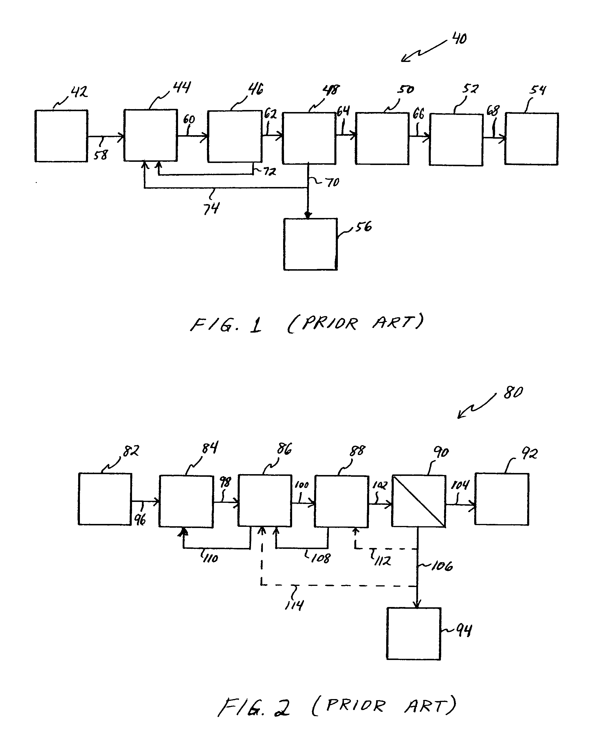
BACKGROUND INFORMATION [0001] 1. Technical Field [0002] The invention is generally related to the field of wastewater treatment. More specifically, the invention relates to novel apparatus and methods of using same which address problems of organic pollutants, nitrogen, phosphorous, and / or coliform bacteria and other microorganism removal from residential, municipal, and / or industrial wastewater. [0003] 2. Background Art [0004] A conventional method for reducing organic material, nitrogen and phosphorous in industrial wastewater is presented in FIG. 1. Prior art embodiment 40 comprises a source of screened, raw wastewater 42, a mixed only anoxic stage 44, an aeration stage 46, a clarifier 48, a filter stage 50, and a chlorination stage 52, the process producing a treated effluent at 54. A waste activated sludge holding tank 56 is also represented. Also illustrated in embodiment 40 are conduits 70, 72, and 74. Conduit 70 routes waste activated sludge from clarifier 48 to waste activa...

Claims


Application Information

Patent Timeline
IPC IPC(8): C02F3/00C02F3/30C02F9/14
CPCB01D61/16B01D2311/04C02F1/444C02F3/1268C02F3/308B01D2311/12Y10S210/903Y10S210/906B01D61/145B01D61/147Y02W10/10
Inventor DEVINE, JEFFREY S.
Owner ALFA LAVAL ASHBROOK SIMON HARTELY INC
Learn More