Biopotential sensor

a biopotential sensor and sensor technology, applied in the field of medical sensors, can solve the problems of difficult data signal acquisition, high electrical impedance of the outermost layer of the skin, and difficulty in obtaining data signals

Inactive Publication Date: 2006-08-03
GENERAL ELECTRIC CO
View PDF6 Cites 26 Cited by
  • Summary
  • Abstract
  • Description
  • Claims
  • Application Information

AI Technical Summary

Benefits of technology

[0008] The object of the invention is to obtain a simple and practical structure for a biopotential sensor. An advantage of the present invention is that the sensor is extremely simple and practical when compared to the prior art. Simple structure means in practice that the invention can be materialized very simply, whereby costs can be kept at reasonably low level.
is that the sensor is extremely simple and practical when compared to the prior art. Simple structure means in practice that the invention can be materialized very simply, whereby costs can be kept at reasonably low level.

Problems solved by technology

Difficulties often arise when measuring weak biopotentials with skin mounted electrodes or sensors.
One problem is that the outermost layer of skin has high electrical impedance.
High electrical impedance reduces signal magnitude so that a data signal may be difficult to obtain when electrical noise is present.
The procedure described above is however time consuming, particularly when several sensors are to be applied and is inconvenient in any clinical situations such as preparing the patient for surgery.

Method used


Image

  • Biopotential sensor
  • Biopotential sensor
  • Biopotential sensor

Examples


Embodiment Construction

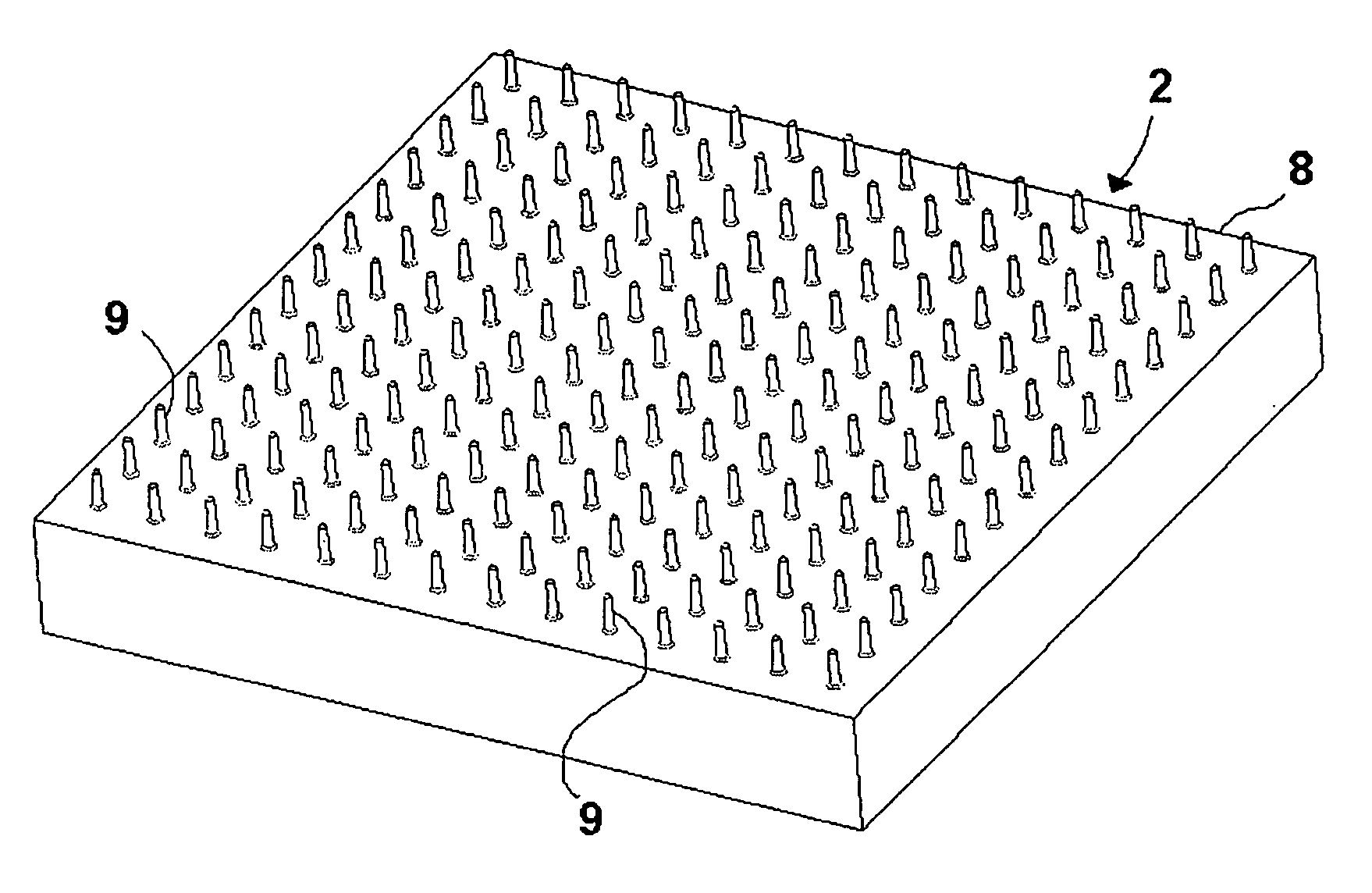
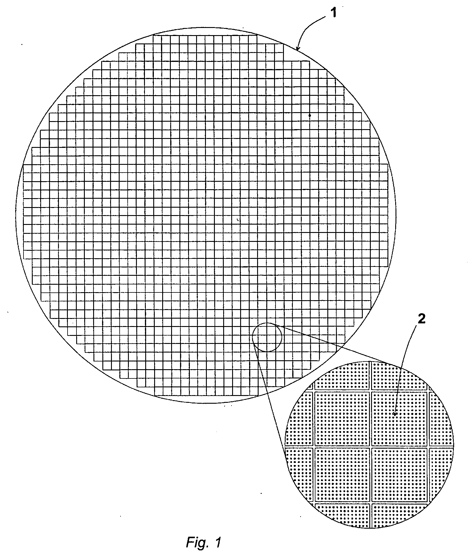
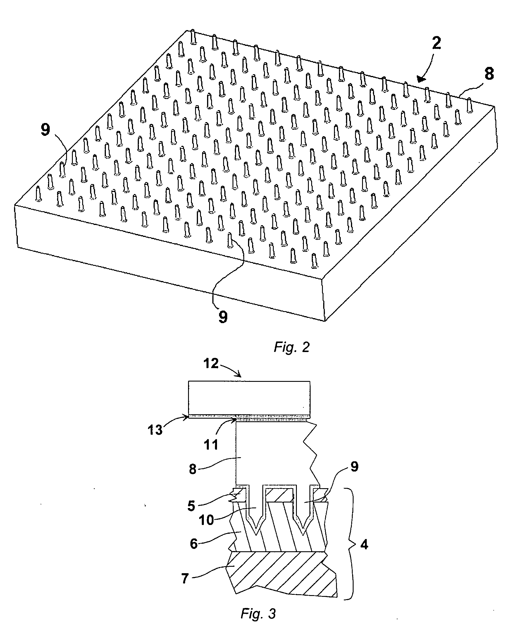
[0014]FIG. 1 shows basic steps of the manufacture of the sensor of the invention. Micromechanic structures are manufactured by etching a material, for example silicon, into the desired shape. This allows the manufacturing of complex structures with extremely small dimensions. The spikes in the biopotential sensor of the invention are etched on a silicon wafer 1, which is thereafter coated with conductive substances to make a suitable skin interface. In order to avoid having to coat each sensor separately, the entire wafer is coated at once. After the coating steps the wafer 1 is diced into sensors 2. This results in a “cube” having a carrier 8 and spikes 9 extending from the top surface of the carrier. The top surface of the carrier and the surfaces of the spikes are coated with a conductive material but the sides are bare Si. Said “cube” formed sensor structure is clearly shown in FIG. 2. The upper edges can be rounded or chamfered to make the coatings reach further down the sides ...


PUM


Abstract

A sensor for measuring biopotential signals from the skin of a patient. The sensor comprises a carrier having a top surface positioned contiguous with the skin of the patient when the sensor is applied to the patient's skin and a bottom surface facing away from the patient when the sensor is applied to the patient's skin. The carrier has further plurality of spikes extending from the top surface for being inserted into the skin of the patient when the sensor is applied to the patient's skin. The sensor further comprises means for obtaining the biopotential signal and for making the biopotential signal available externally of the sensor. The carrier is manufactured of non-conductive material and the non-conductive material is made conductive to form electrical connection between the top and bottom surfaces of the carrier.

Description

BACKGROUND AND SUMMARY [0001] The invention relates to medical sensors, which are applied to a patient's skin for monitoring biopotentials and in particular to sensors that penetrate the patient's skin to make the skin more electrically permeable. [0002] Diagnostic tests, treatments and the presence of illness require measuring and monitoring electrical signals generated by the physiological functioning of a patient. Typical electrical signals or biopotentials that are commonly monitored are those producing electrocardiograms (ECG) from the heart, electroencephalograms (EEG) from the brain and electromylograms (EMG) from the muscles. Such signals are of relatively low level and may be weak, such as 100 microvolt or less signals present in an electroencephalogram (EEG). The frequency range of the signals extends from 0.05 for electro-cardiograms to 3000 Hz for brain stem evoked potentials. [0003] Skin mounted monitoring sensors are typically used to obtain the biopotentials. The huma...

Claims


Application Information

Patent Timeline
Patent Type & Authority Applications(United States)
IPC IPC(8): A61B5/04
CPCA61B5/0492A61B2562/0209A61B2562/046A61B2562/125A61B5/296
Inventor KALL, MAGNUSKALVESTEN, EDVARD
Owner GENERAL ELECTRIC CO
Why Eureka
Try Eureka