Method and apparatus for removing contaminants from conduits and fluid columns
- Summary
- Abstract
- Description
- Claims
- Application Information
AI Technical Summary
Benefits of technology
Problems solved by technology
Method used
Image
Examples
first embodiment
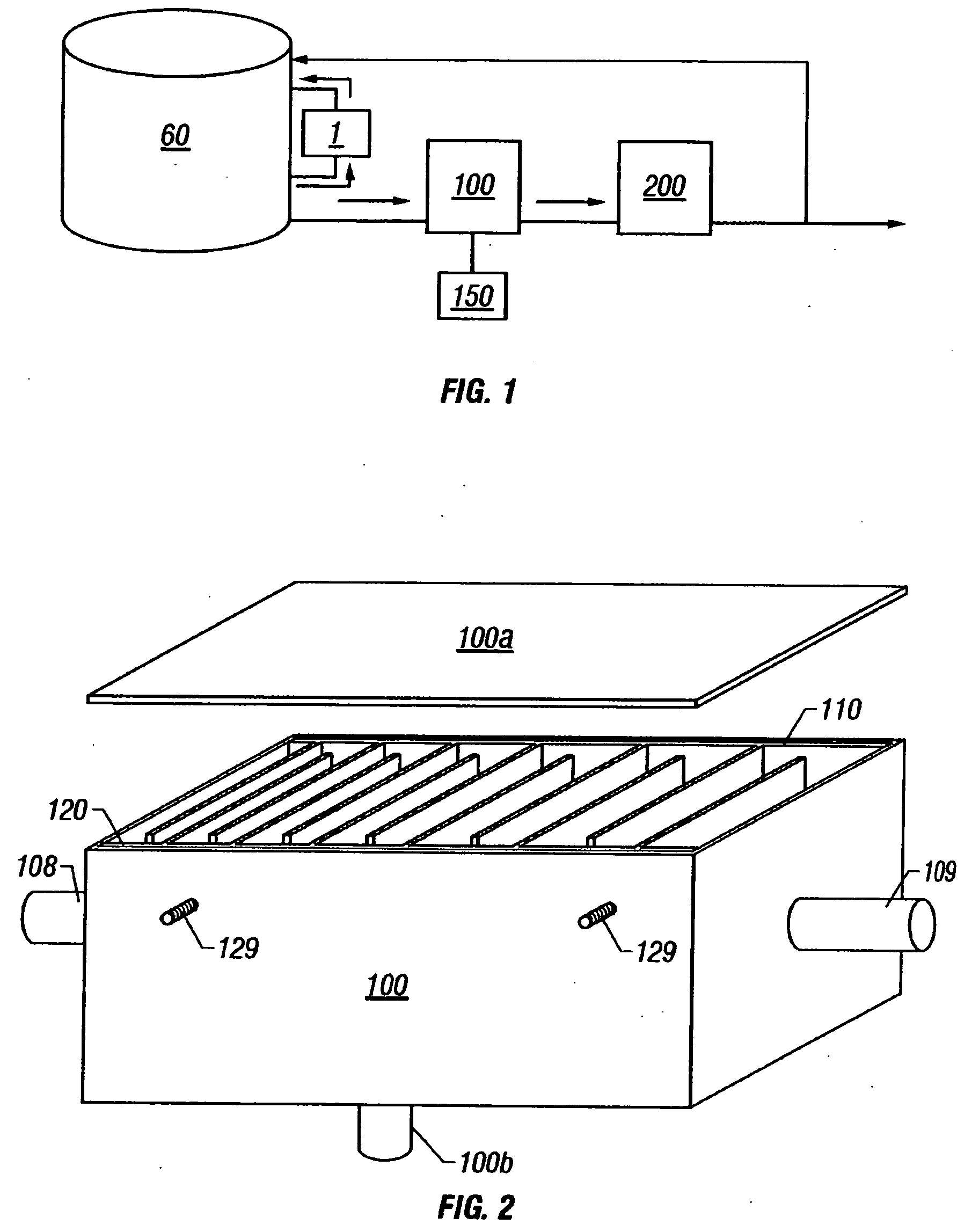
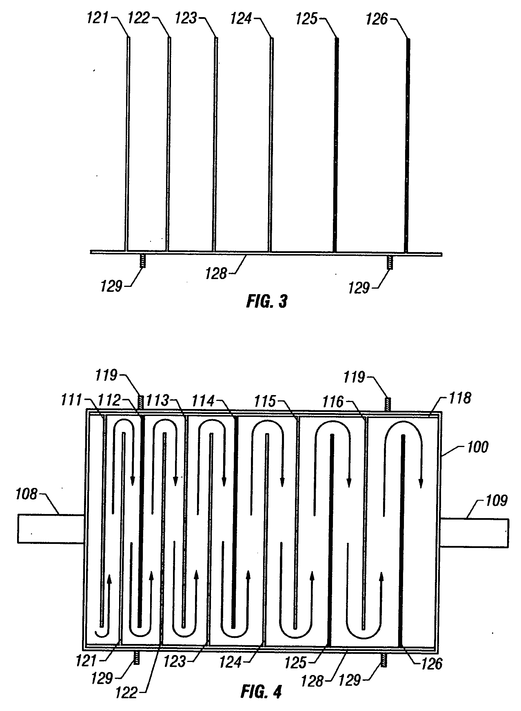
[0079]FIG. 2 depicts an open top view of the contaminant separation reactor of the instant invention. Opposing electrodes 110 and 120 are shown within reactor housing 100 defining an interior chamber established by a fluid impervious boundary wall with an inner surface and having inlet and outlet ports. Each electrode is comprised of a plurality of parallel, spaced apart plates of an electrically conductive material coupled to a common buss bar wherein the cavities between the plates are non-uniform and the plates are fixed in a perpendicular orientation to the buss bar. The electrode plates are arranged in a parallel pattern that provides for progressively greater distances between the facing surfaces of each adjacent plate. The plates of the opposing electrodes interleave in a parallel orientation to define a flow path from the inlet port to the outlet port and form a series of cavities of non-uniform volume. As such, the flow path of a fluid is substantially orthogonal to the dir...
second embodiment
[0090]FIG. 5 is a top view of a contaminant separation sector utilized in the contaminant separation reactor of the instant invention. As used herein, a contaminant separation sector shall mean a distinct fluid treatment unit comprising a pair of electrodes, each electrode comprising a plurality of parallel, spaced-apart plates of an electrically conductive material coupled to a common buss bar wherein the spacing between the plates of each contaminant separation sector is uniform. Plates 221, 223, 225 and 227 are typically comprised of an electrically conductive material having a uniform thickness, length and height and fixed as a parallel array to buss bar 229. Plates 222, 224, 226 and 228 are typically comprised of an identical electrically conductive material having a uniform thickness, length and height and fixed as a parallel array to buss bar 230.
[0091] Buss bar 229 facilitates the flow of electricity to the parallel array of plates 221, 223, 225 and 227 while buss bar 230 fa...
third embodiment
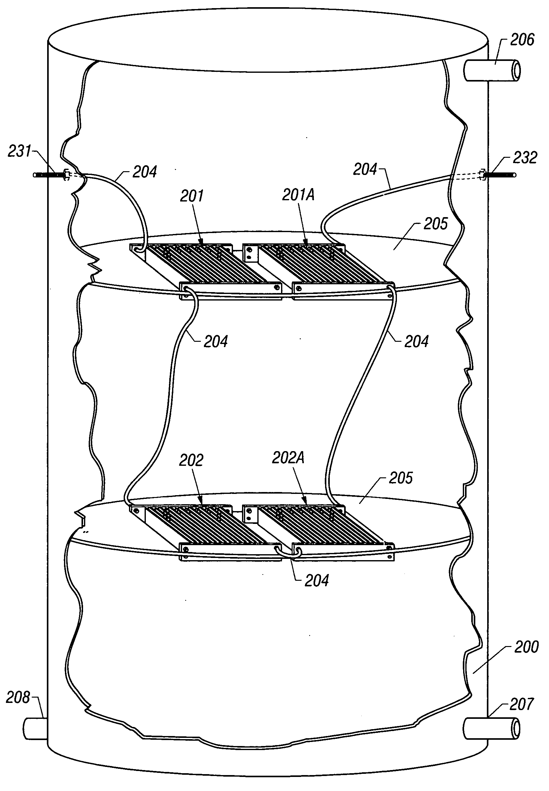
[0114]FIG. 7 depicts a cut-away view of the instant invention and shows a plurality of contaminant separation sectors 201 and 201A arranged within the interior chamber of the housing such that the electrodes of the contaminant separation sectors are disposed in a substantially coplanar array in a distinct layer. The plates of the electrodes interleave and form a series of cavities between the facing surfaces of the electrode plates to define a flow path from the inlet port to the outlet port of the housing. Each electrode of a contaminant separation sector is comprised of a plurality of parallel, spaced apart plates coupled to a common buss bar wherein the spacing between the plates is uniform. The individual contaminant separation sectors 201 and 201A are connected in series by electrical jumpers 204 within reactor housing 200, said housing defining an interior chamber established by a fluid impervious boundary wall with an inner surface and having inlet and outlet ports.
[0115] The...
PUM
| Property | Measurement | Unit |
|---|---|---|
| Electrical conductivity | aaaaa | aaaaa |
| Power | aaaaa | aaaaa |
| Flow rate | aaaaa | aaaaa |
Abstract
Description
Claims
Application Information
 - R&D
- Intellectual Property
- Life Sciences
- Materials
- Tech Scout
- Unparalleled Data Quality
- Higher Quality Content
- 60% Fewer Hallucinations
Browse by: Latest US Patents, China's latest patents, Technical Efficacy Thesaurus, Application Domain, Technology Topic, Popular Technical Reports.
© 2025 PatSnap. All rights reserved.Legal|Privacy policy|Modern Slavery Act Transparency Statement|Sitemap|About US| Contact US: help@patsnap.com


