Variable gain amplifying apparatus and wireless communication apparatus

a variable gain amplifying and wireless communication technology, applied in the direction of amplifiers, gain control, amplification control details, etc., can solve the problem of discontinuous phase shift of the signal outputted from the variable gain amplifying apparatus

Inactive Publication Date: 2006-08-10
PANASONIC CORP
View PDF7 Cites 9 Cited by
  • Summary
  • Abstract
  • Description
  • Claims
  • Application Information

AI Technical Summary

Benefits of technology

[0041] In view of the above problem, the object of the present invention is to provide a variable gain amplifying apparatus capable of sufficiently alleviating the situation in which the phase outputted from the variable gain amplifying apparatus is shifted in a discontinuous manner even when the gain of the variable gain amplifying apparatus is switched, and a wireless communication apparatus.

Problems solved by technology

That is, there is a problem such that the phase of the signal outputted from the variable gain amplifying apparatus is shifted in a discontinuous manner when the gain of the variable gain amplifying apparatus is switched.

Method used


Image

  • Variable gain amplifying apparatus and wireless communication apparatus
  • Variable gain amplifying apparatus and wireless communication apparatus
  • Variable gain amplifying apparatus and wireless communication apparatus

Examples


first embodiment

[0198] First, the first embodiment will be described.

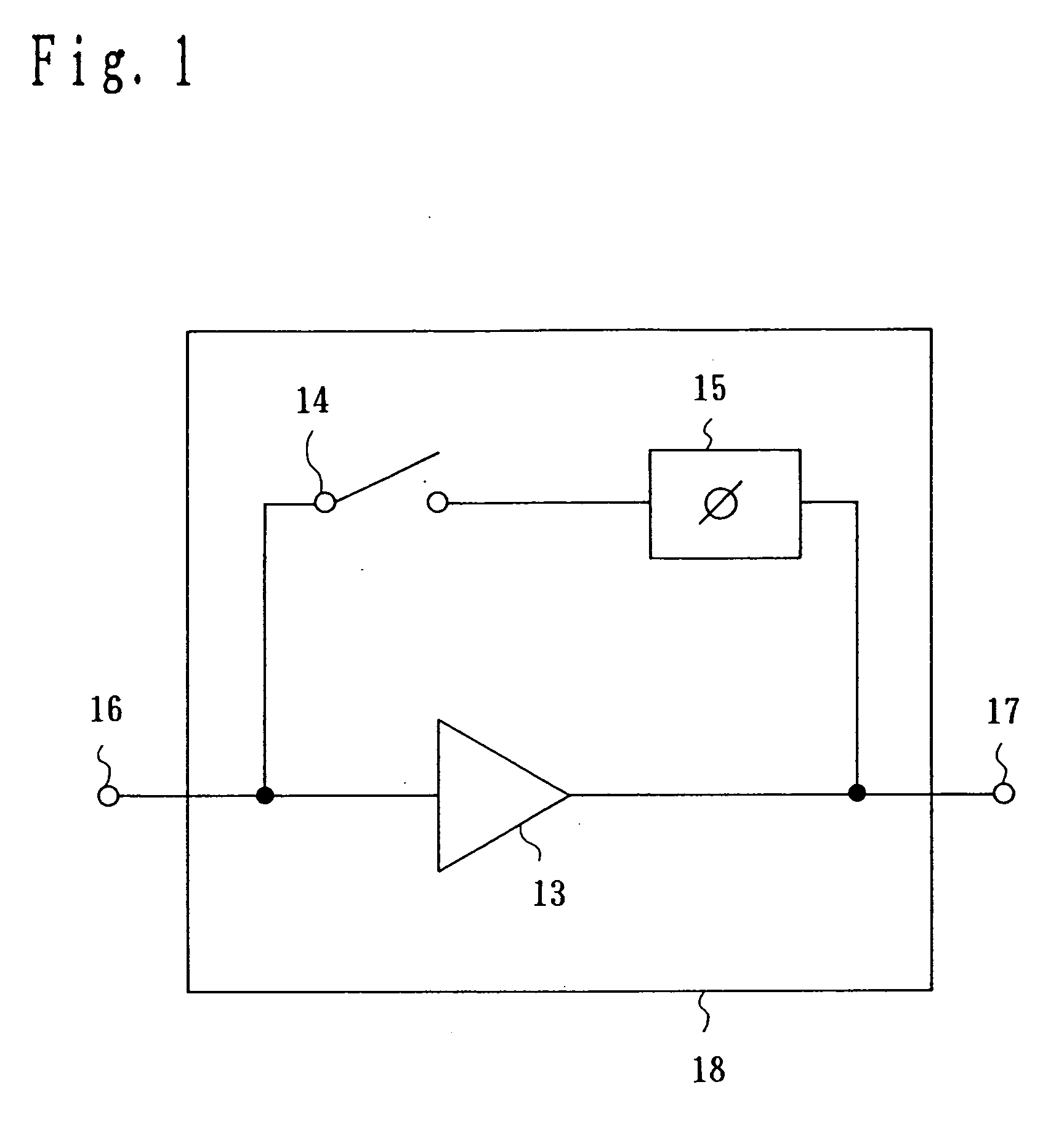
[0199] A variable gain amplifying apparatus 18 of this embodiment is shown in FIG. 1. The variable gain amplifying apparatus 18 is used as, for example, a variable gain amplifying apparatus 4 of a cellular phone terminal of FIG. 21.

[0200] The variable gain amplifying apparatus 18 is comprised of an amplifier 13, a switching element 14 and a phase shifter 15.

[0201] The amplifier 13 has its input connected to an input terminal 16 and its output connected to an output terminal 17. The switching element 14 is connected at one end to the input of the amplifier 13 and connected at the other end to one end of the phase shifter 15. The other end of the phase shifter 15 is connected to the output of the amplifier 13. The input terminal 16 is a terminal to which the receive signal outputted from the front stage of a duplexer 2 of FIG. 21 is inputted, and the output terminal 17 is a terminal for outputting the signal amplified in the vari...

second embodiment

[0222] The second embodiment will now be described.

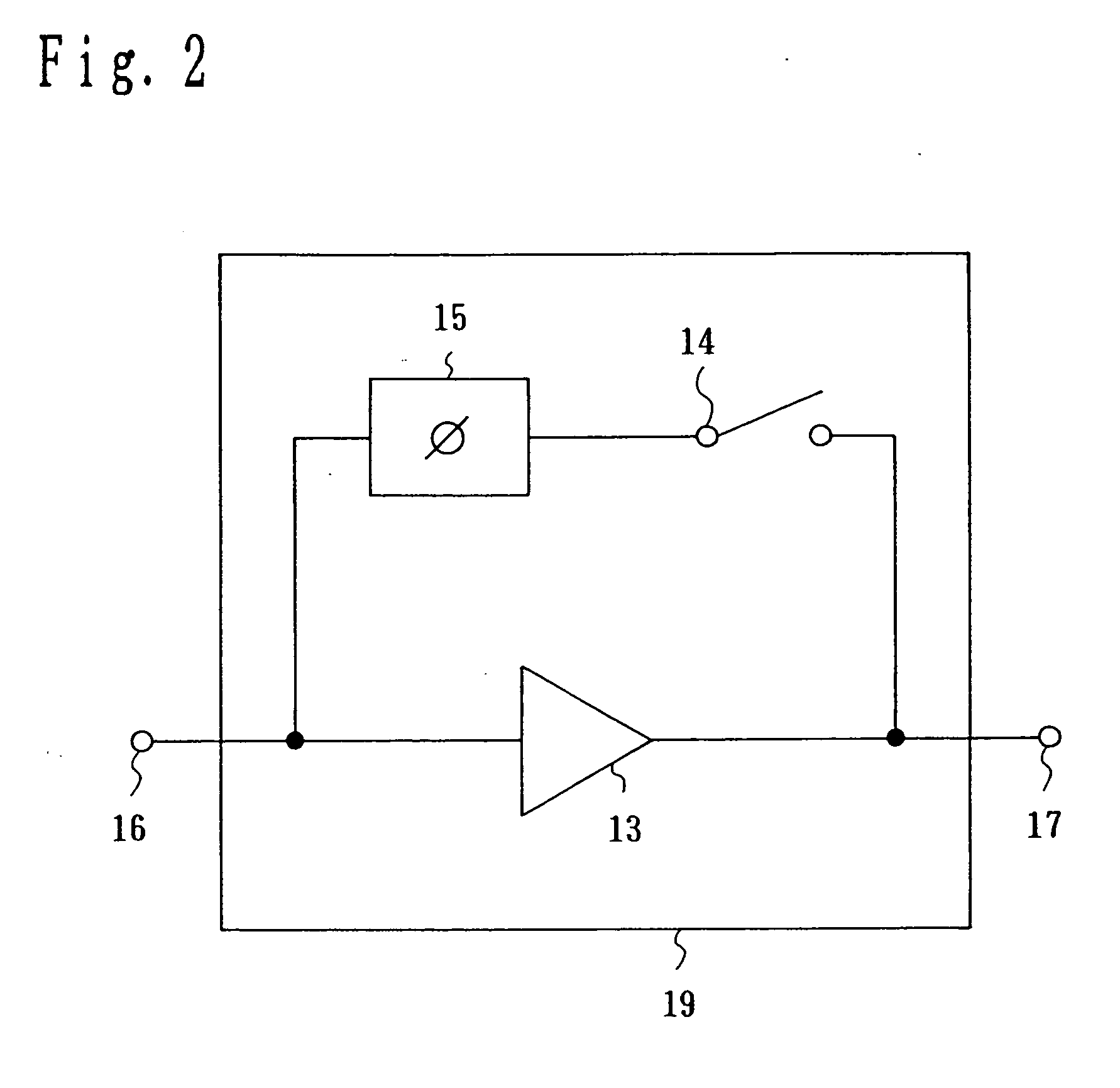
[0223] A variable gain amplifying apparatus 24 of this embodiment is shown in FIG. 4. The variable gain amplifying apparatus 24 is used as, for example, the variable gain amplifying apparatus 4 of the cellular phone terminal of FIG. 21. Furthermore, the parts identical to those of the first embodiment are given same symbols and descriptions thereof are not presented here.

[0224] The variable gain amplifying apparatus 24 is comprised of the amplifier 13, the switching element 14, the phase shifter 15, the switching element 20, a feedback circuit 22 and a switching element 23.

[0225] The amplifier 13 has its input connected to the input terminal 16 and its output connected to the output terminal 17. The switching element 14 is connected at one end to the input of the amplifier 13, and connected at the other end to one end of the phase shifter 15. The other end of the phase shifter 15 is connected to one end of the switching element 2...

third embodiment

[0236] The third embodiment will now be described.

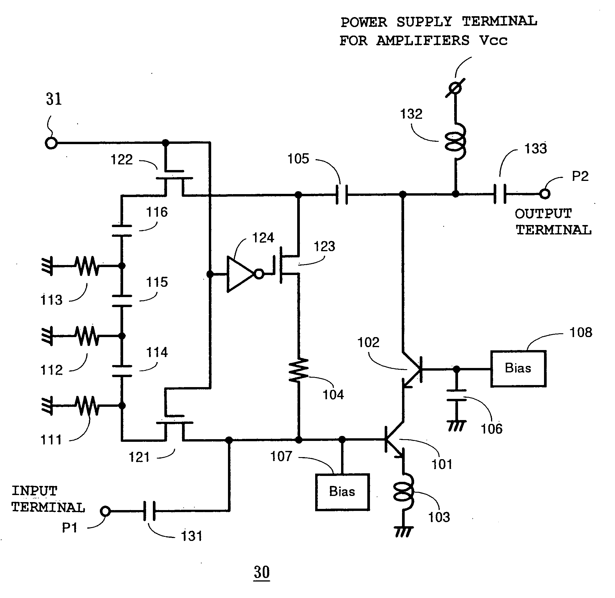
[0237]FIG. 6 is a circuit diagram of a variable gain amplifying apparatus 30 of this embodiment.

[0238] In the variable gain amplifying apparatus 30 shown in FIG. 6, an input terminal P1 is connected to one end of an input side capacitor 131 for breaking direct currents, and the other end of the input side capacitor 131 is connected to one end of a switching element 121 and the base of a transistor 101. A bias power circuit 107 is connected to the base of the transistor 101, the emitter of the transistor 101 is grounded through an inductor 103 for widening the input dynamic range, and the collector of the transistor 101 is connected to the emitter of a transistor 102. The base of the transistor 102 is connected to a bias power circuit 108 and a bypass capacitor 106 which is grounded. The collector of the transistor 102 is connected to one end of an output side capacitor 133 for breaking direct currents and one end of a negative feed...


PUM


Abstract

A variable gain amplifying apparatus has an amplifier, one or more first switching elements connected in parallel to the amplifier, and a phase shifter connected in series to the first switching element. The first switching element is enabled if the level of an input signal or an output signal is higher than a predetermined level, and the first switching element is disabled if the level of the input signal or the output signal is equal to or lower than the predetermined level. The amplifier does not operate when the first switching element is enabled, and the amplifier operates when the first switching element is disabled, and the amount of phase shift when the input signal is passed through the amplifier and phase shifter is substantially equal to the amount of phase shift when the input signal is passed through the first switching element.

Description

[0001] This application is a continuation of U.S. patent application Ser. No. 10 / 263,252, filed Oct. 2, 2002, the contents of which are incorporated herein by reference.BACKGROUND OF THE INVENTION [0002] 1. Field of the Invention [0003] The present invention relates to a variable gain amplifying apparatus having a gain control function, and a wireless communication apparatus. [0004] 2. Related Art of the Invention [0005] A pre-stage amplifier of a reception device in a radio system represented by cellular phones needs to have low-noise and high-gain characteristics if receiving very weak signals, and the pre-amplifier needs to have low-distortion and low-gain characteristics if receiving large signals. [0006] Particularly, in current mobile communications, since the electric field intensity during reception varies significantly depending on the distance between a base station and a mobile station, the reception device requires a large dynamic range, and consequently the pre-amplifie...

Claims


Application Information

Patent Timeline
Patent Type & Authority Applications(United States)
IPC IPC(8): H03F1/14H03G1/00H03G3/10H04B1/40
CPCH03G1/0088
Inventor NAKATANI, TOSHIFUMIITOH, JYUNJINAKANO, HIDEO
Owner PANASONIC CORP
Why Eureka
Try Eureka