Tuning device and radio-wave corrected timepiece

a tuning device and radio wave correction technology, applied in the field of compact, high-performance tuning apparatus, can solve the problems of difficult to achieve stable tuning circuit, difficult to vary the tuned frequency over a wide range, difficult to achieve high q value tuning circuit, etc., to achieve high-sensitivity tuning and improve the gain of the antenna

Inactive Publication Date: 2006-08-10
CITIZEN WATCH CO LTD
View PDF21 Cites 36 Cited by
  • Summary
  • Abstract
  • Description
  • Claims
  • Application Information

AI Technical Summary

Benefits of technology

[0027] Because of this, since it is possible to select the optimum off resistance of the semiconductor switch in accordance with the electrostatic capacitance of the connected capacitor, it is possible to achieve a high-sensitivity tuning apparatus.
[0028] Additionally, in the present...

Problems solved by technology

However, because a variable-capacitance diode makes use of the depletion layer of a semiconductor PN junction, a leakage current exists, making it impossible to achieve a tuning circuit with a high Q value.
Also, because the Q value changes with a change in the electrostatic capacitance, it is difficult to achieve a stable tuning circuit.
Additionally, because of the limited variable capacitance range of a variable-capacitance diode, it is difficult to vary the tuned frequency over a wide range.
However, because the plurality of variable-capacitance diodes formed on the semiconductor substrate make use of the depletion region of a PN junction, as noted above, a leakage...

Method used


Image

  • Tuning device and radio-wave corrected timepiece
  • Tuning device and radio-wave corrected timepiece
  • Tuning device and radio-wave corrected timepiece

Examples


first embodiment

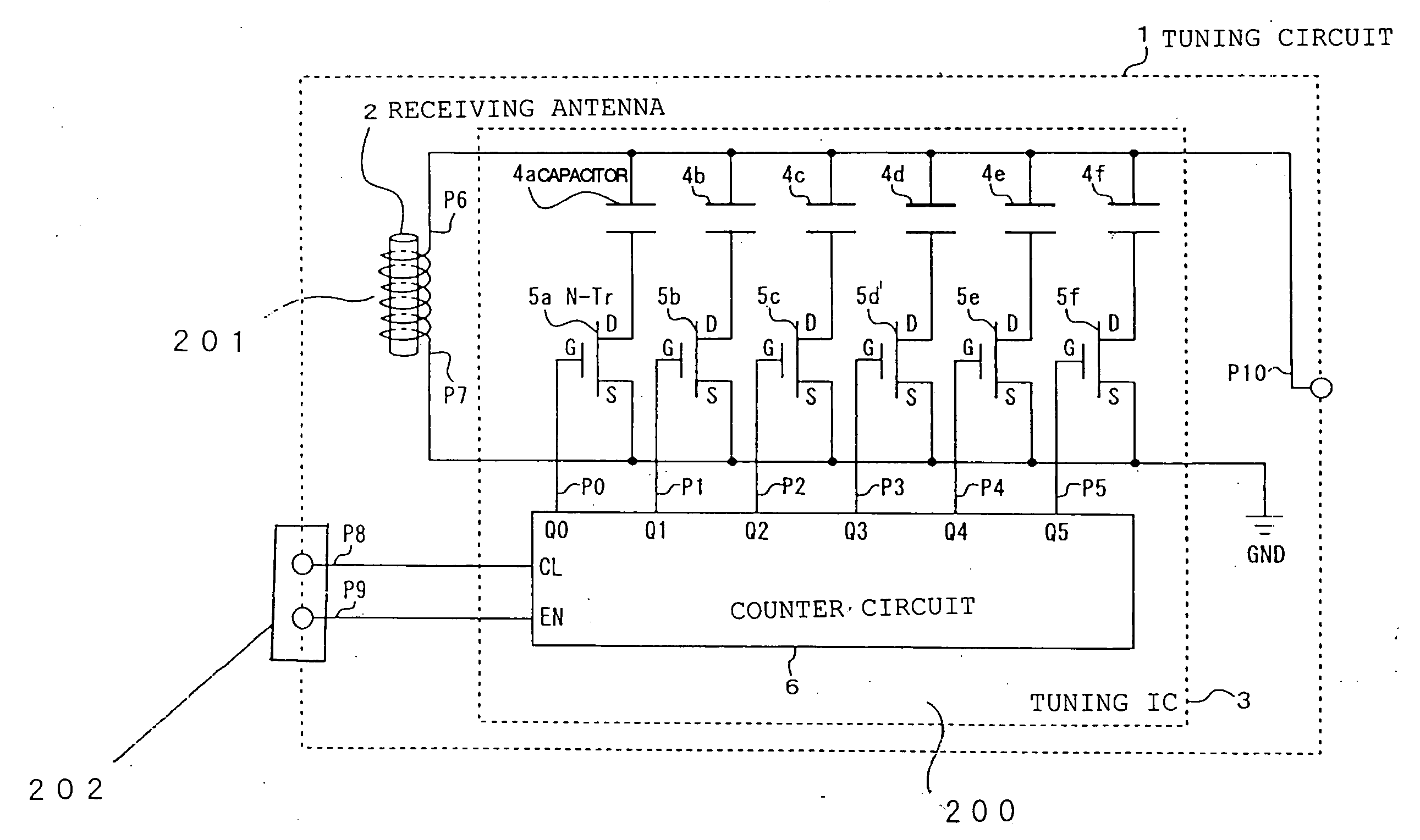
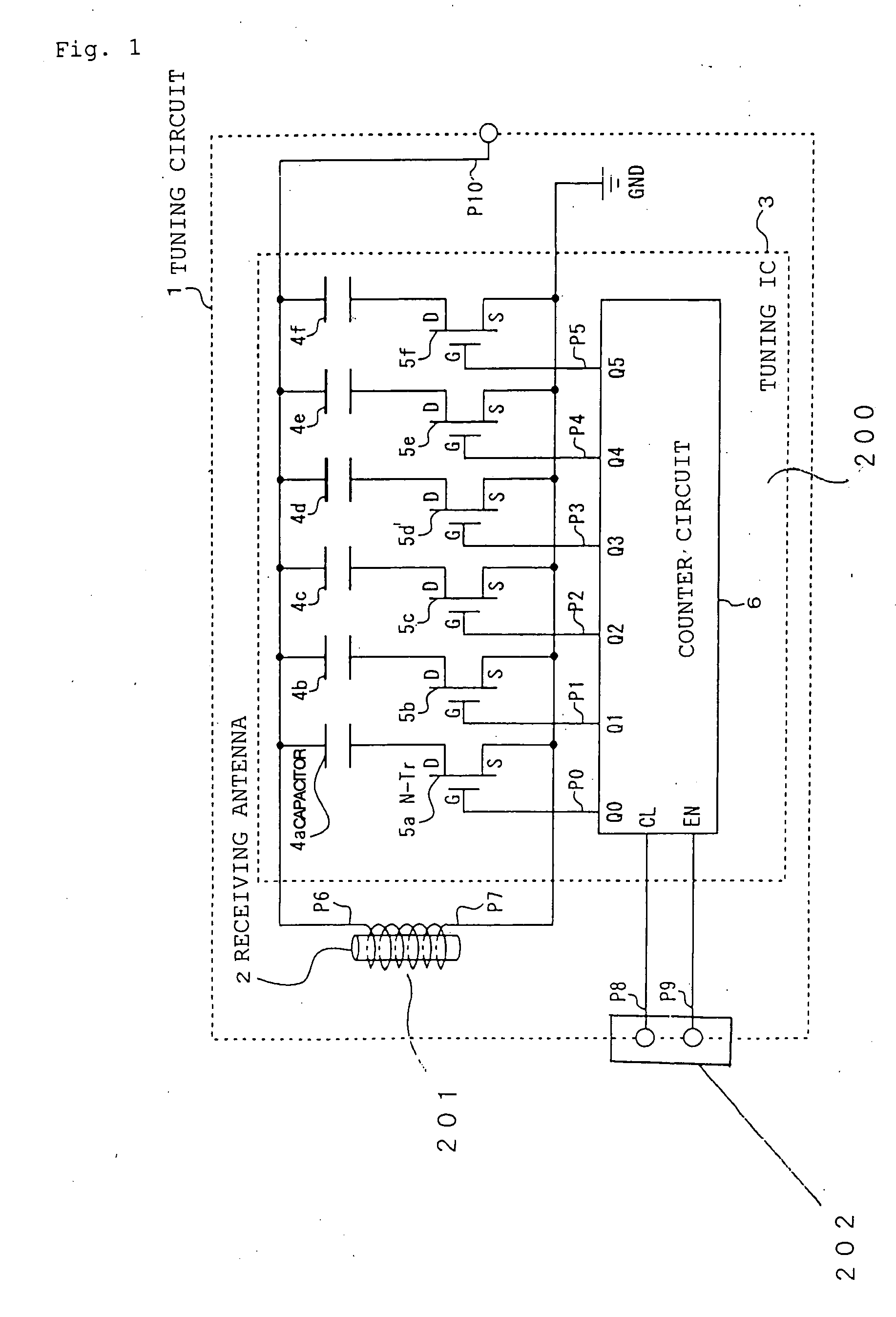
[0068] Embodiments of the present invention are described in detail below, based on the drawings. FIG. 1 is a block diagram showing an example of the configuration of a tuning circuit 1, which is the present invention.

[0069] In the FIG. 1, a tuning circuit 1, for example, which being suitable for use in the receiver section of a radio-controlled timepiece is disclosed.

[0070] The configuration thereof in the drawing, has a semiconductor substrate 200, which is provided with a plurality of semiconductor switches 5, a plurality of first capacitors 4, which are each connected in series with the plurality of semiconductor switches 5, and a switch controlling means 6, which controls the opening and closing of the semiconductor switches 5, and a plurality of first coils 201 forming an antenna 2 and connected in parallel with each of the first capacitors 4, wherein, in response to a received station selection command signal for a standard radio wave including time information, the switch c...

second embodiment

[0183] Additionally, in the tuning circuit 1 of the present invention, the second capacitor 7 is preferably subjected to control that is different from the control to which the first capacitors 4 are subjected, and it is desirable that the capacitance of the second capacitor 7 is different from each one of the capacitance of the first capacitor 4, respectively.

[0184] In particular, it is desirable that the electrostatic capacitance of the second capacitor be quite a bit larger than the electrostatic capacitance of the first capacitor.

[0185] At least one of the second capacitors 7 in the second embodiment of the present invention has a suitable switching means 5f, and the configuration is such that the switching means 5f is controlled by the controlling means 6.

[0186] In this embodiment, the switching means 5f can be a semiconductor switch 5 provided on the semiconductor substrate 200 in the same manner as in the first embodiment, or can also be formed at a position at a distance f...

third embodiment

[0207]FIG. 6 describes the relationship between a radio-controlled timepiece 40 and a transmitting station 45, which transmits a standard radio wave as shown in the present invention, in that a tuning device including a tuning circuit 1 is incorporated.

[0208] In FIG. 6, 40 denotes an analog-display-type radio-controlled timepiece. 41 is an metal exterior part made of a metallic material, 42 is a display as a display means, 42a is a second hand, 42b is a minute hand, 42c is an hour hand and 42d is a date display that indicates the date. The reference 2 indicates an ultra-compact receiving antenna, which is preferably disposed at the 12-o'clock position within the metal exterior part 41. 43 is a stem used to correct the time and date, and 44 is a band for the purpose of holding the watch on the hand of a user (not illustrated).

[0209] The reference numeral 45 is a transmitting station that transmits a standard radio wave. 46 is a transmitting antenna that radiates the standard radio w...


PUM


Abstract

A tuning apparatus is provided, wherein the on and off resistances of semiconductor switches within an tuning IC are optimized, so as to provide high sensitivity and superior stability, a wide range of tuned frequency variation, compactness and high performance. The tuning apparatus has a tuning circuit, which has N-channel MOS transistors (N transistors) 5a through 5f, serving as a plurality of semiconductor switches, and a counter circuit 6, which controls the opening and closing of the N transistors, a plurality of capacitors 4a through 4f, which are each connected in series with the plurality of N transistors, and a receiving antenna 2 wherein the total electrostatic capacitance of the plurality of capacitors is varied by the opening and closing of the plurality of N transistors, thereby varying the frequency tuned by the plurality of capacitors and the receiving antenna.

Description

BACKGROUND OF THE INVENTION [0001] 1. Field of the Invention [0002] The present invention relates to a compact, high-performance tuning apparatus, which receives a radio wave or the like and to an improvement on a method for receiving in a radio-controlled timepiece using the above-noted tuning apparatus. [0003] 2. Background Art [0004] In the past, the electronic tuning apparatus used in an electronic tuner of a receiver or in the oscillator of a transmitter generally used a variable-capacitance diode, whereby a voltage applied to the variable-capacitance diode is controlled so as to vary its equivalent electrostatic capacitance, thereby varying the tuned frequency. Because this method, in addition to using a compact, low-cost variable-capacitance diode, enables easy variation of the tuned frequency by controlling the applied voltage, it has an advantage in enabling compact and low-cost implementation of tuners or transmitting circuits. However, because a variable-capacitance diode...

Claims


Application Information

Patent Timeline
IPC IPC(8): G04C11/02G04G5/00G04G21/04G04R20/00G04R20/10H03J3/20H04B1/18
CPCG04G5/002G04G21/04H03J2200/10H04B1/18G04R60/12G04R20/10
Inventor IHARA, TAKASHI
Owner CITIZEN WATCH CO LTD
Why Eureka
Try Eureka