Imaging device

a technology of image pickup and image, which is applied in the field of image pickup devices, can solve the problems of only being used rarely, unable to achieve simple levitation control, and not excelling at position recognition of samples except spherical samples, etc., and achieves the effect of capture image and further obtaining the contrast of samples against the background

Inactive Publication Date: 2006-08-10
IHI AEROSPACE CO LTD
View PDF3 Cites 2 Cited by
  • Summary
  • Abstract
  • Description
  • Claims
  • Application Information

AI Technical Summary

Benefits of technology

[0009] The present invention has been made in view of the subject in the conventional art, and an object of the present invention is to provide an image pickup device which can obtain a contrast of a sample against a background even if the sample becomes incandescent due to a high temperature, and can output position information required for levitation control on not only a spherical sample but also a sample with a further complicated shape in real time, thereby being capable of specifying an instant at which a sample with a complicated shape changes to a spherical one visually, that is, determining an instant at which the sample melts visually.
[0010] As the result of repeating keen examination for accomplishing the above object, the present inventors have found that the above object can be accomplished by combining a CMOS camera or a CCD camera for photographing a sample which is provided with a telecentric lens, a background light source which irradiates light with a wavelength of 400 to 600 nm on a sample, and a digital signal processor which performs image processing for edge enhancement in real time, and therefore have completed the present invention.
[0016] Furthermore, since light with a wavelength of 400 to 600 nm is irradiated from the background light source, even if the sample becomes incandescent due to a high temperature, contrast of the sample against a background is eventually obtained. In addition, as regards a captured image of a sample, since the digital signal processor performs image processing for enhancing an edge of the image in real time to output a position of center of gravity required for levitation control, levitation melting of the sample with a complicated shape is made possible, so that an instant at which the sample with a complicated shape put in the levitation state changes to a spherical shape one can be determined visually.
[0017] In the image pickup device according to a preferable embodiment of the present invention, since the constitution described above is adopted, interference of light between lenses of the CMOS camera or the CCD camera can be avoided so that the captured image is further sharpened. In the image pickup device according to a more preferable embodiment of the present invention, since the constitution described above is adopted, contrast of a sample against a background can be obtained further surely.

Problems solved by technology

In the conventional art, however, since a position of the center of gravity of the sample is not calculated in the former position recognizing method, the method does not excel at accuracy in position recognition of a sample except a spherical one.
As a result, there is such a problem that it becomes considerably difficult or impossible to perform levitation control on a simple.
On the other hand, in the latter position recognizing method, the position of the center of gravity of a sample is calculated, but since it takes much time to perform image processing and a sampling speed required for levitation control can not be secured, there is such a problem that the latter method can be used only rarely.
Further, in case that a halogen lamp is used for the background light, when the sample becomes incandescent due to a high temperature, it is impossible to obtain a contrast of a sample against a background, so that laser light is adopted as the background light in the latter position recognizing method (see FIG. 3).
However, for convenience of using a CCD camera, there is a problem about interference of laser light due to a camera lens.
There is such a problem that it is difficult to specify a melting time correctly.

Method used


Image

  • Imaging device
  • Imaging device
  • Imaging device

Examples


Embodiment Construction

[0021] The present invention will be explained below in detail according to an embodiment, but a detailed constitution of the present invention is not considered limited to only the following embodiment.

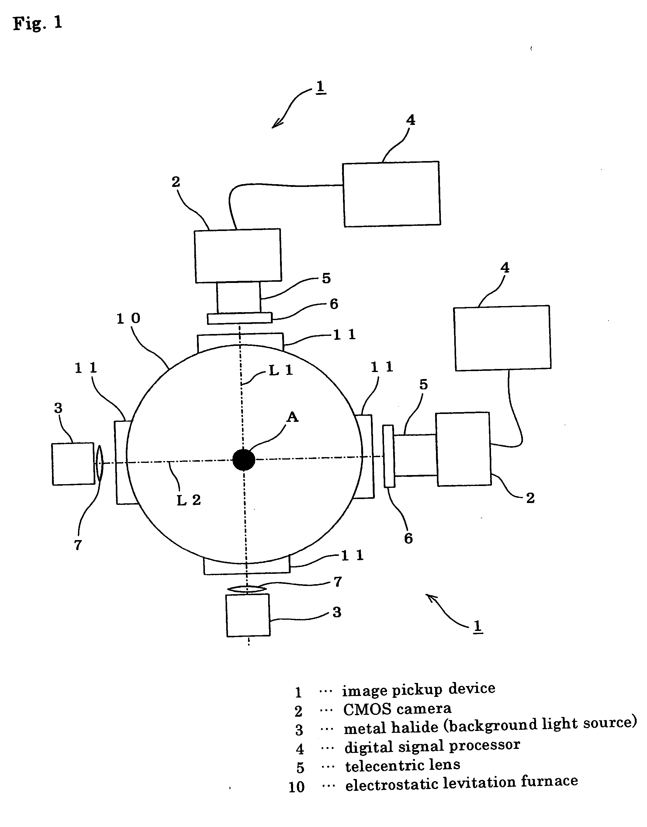
[0022] As schematically shown in FIG. 1, an electrostatic levitation furnace 10 is interiorly formed of an approximate cylindrical space, and the center of the space is set as a levitation position for a sample A. The electrostatic levitation furnace 10 is provided on a peripheral wall thereof with a plural of ports for access (not shown), and opening portions 11 are provided so as to correspond to arrangement of the ports for access.

[0023] An image pickup device 1 which monitors the sample A to be subjected to heating process in its levitation state within the electrostatic levitation furnace 10 to output position information of the sample is provided with a CMOS camera 2 which is mounted at the port for access in the vicinity of the opening portion 11 to photograph the sample A p...


PUM


Abstract

The present invention is an image pickup device provided with a CMOS camera which is provided with a telecentric lens to photograph a sample put in a levitation state at the center inside an electrostatic levitation furnace, a metal halide light source which is positioned on the opposite side of the sample from the CMOS camera to irradiate light with a wavelength of 400 to 450 nm toward the sample, and a digital signal processor which performs image processing for enhancing an edge of an image captured by the CMOS camera in real time to output a position of center of gravity of the sample put in the levitation state, where a blue filter is attached to the CMOS camera. Even if the sample becomes incandescent due to a high temperature, contrast of the sample against a background can be obtained by the image pickup device. In addition, position information required for levitation control of a sample with a complicated shape is outputted by the image pickup device so that an instant at which the sample with a complicated shape changes to a spherical shape one can be specified visually.

Description

TECHNICAL FIELD [0001] The present invention relates to an image pickup device which is used to determine an instant at which a sample is melted while recognizing a position of the sample put in a levitation state when performing heating process on the sample in an electrostatic levitation furnace. BACKGROUND ART [0002] The electrostatic levitation furnace, after charging a sample inputted between main electrodes utilizing electrode contact, ultraviolet ray irradiation, or heating, puts the sample to a levitation state by an electrostatic field generated between the main electrodes, while maintaining the sample at a predetermined position by controlling a potential between the main electrodes or auxiliary electrodes, and irradiates laser light on the sample to heat and melt the same. By cooling and solidifying the sample thus heated and melted, crystals can be produced in a state that external interference has been excluded. [0003] It is necessary to control levitation of a sample s...

Claims


Application Information

Patent Timeline
Patent Type & Authority Applications(United States)
IPC IPC(8): G06K9/00G06K9/40G01B11/00F27B14/04F27B17/00F27D19/00F27D21/02G06T1/00H04N7/18
CPCF27B17/0016F27D19/00F27D21/02
Inventor ASAHI, HIROAKIKAWASAKI, KAZUNORI
Owner IHI AEROSPACE CO LTD
Why Eureka
Try Eureka