System and method for reducing vehicle emissions and/or generating hydrogen

a technology of vehicle emissions and hydrogen, applied in the direction of engines, machines/engines, mechanical equipment, etc., can solve the problems of negating a significant portion of energy savings, reducing fuel economy, and electric load, and achieve the effect of reducing emissions from an internal combustion engine without increasing fuel consumption

Inactive Publication Date: 2006-08-17
SULLIVAN JOHN TIMOTHY
View PDF38 Cites 51 Cited by
  • Summary
  • Abstract
  • Description
  • Claims
  • Application Information

AI Technical Summary

Benefits of technology

[0012] It is accordingly a first objective of the invention to provide a system and method for reducing emissions from an internal combustion engine without increasing fuel consumption.

Problems solved by technology

However, they have the disadvantage of increasing the electrical load on the engine, resulting in decreased fuel economy.
However, use of the energy to pre-heat a catalytic converter at start-up, as proposed in the above-discussed U.S. Pat. No. 5,968,456, is not the best use for the re-captured energy, and in fact negates a significant portion of the energy savings since (i) resistance heating is not very energy efficient, and (ii) the added electrical load on the engine at start-up requires a much higher system energy capacity, including higher capacity batteries.
The need for higher capacity batteries increases the weight of the vehicle and decreases fuel efficiency.

Method used


Image

  • System and method for reducing vehicle emissions and/or generating hydrogen
  • System and method for reducing vehicle emissions and/or generating hydrogen
  • System and method for reducing vehicle emissions and/or generating hydrogen

Examples


Embodiment Construction

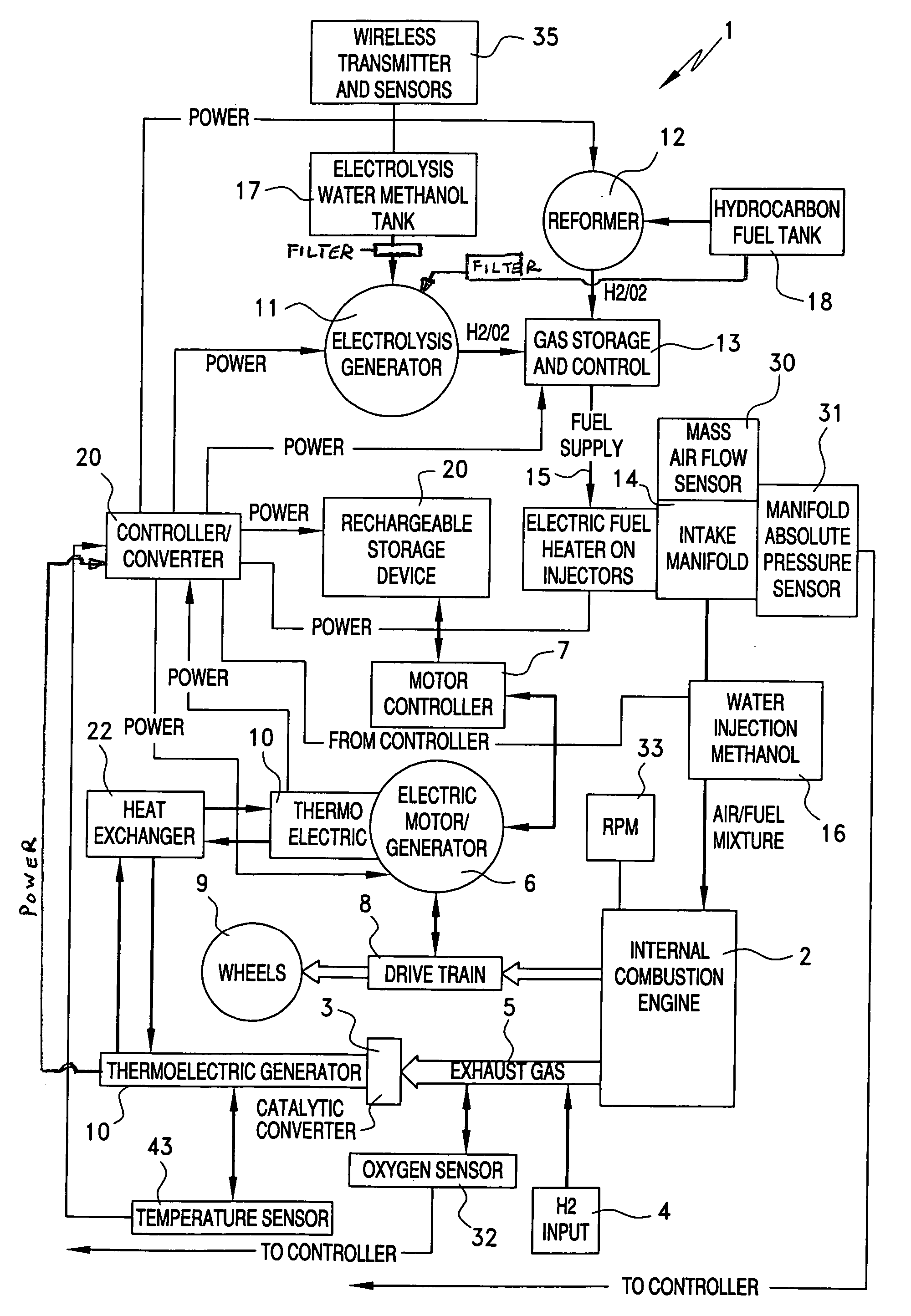
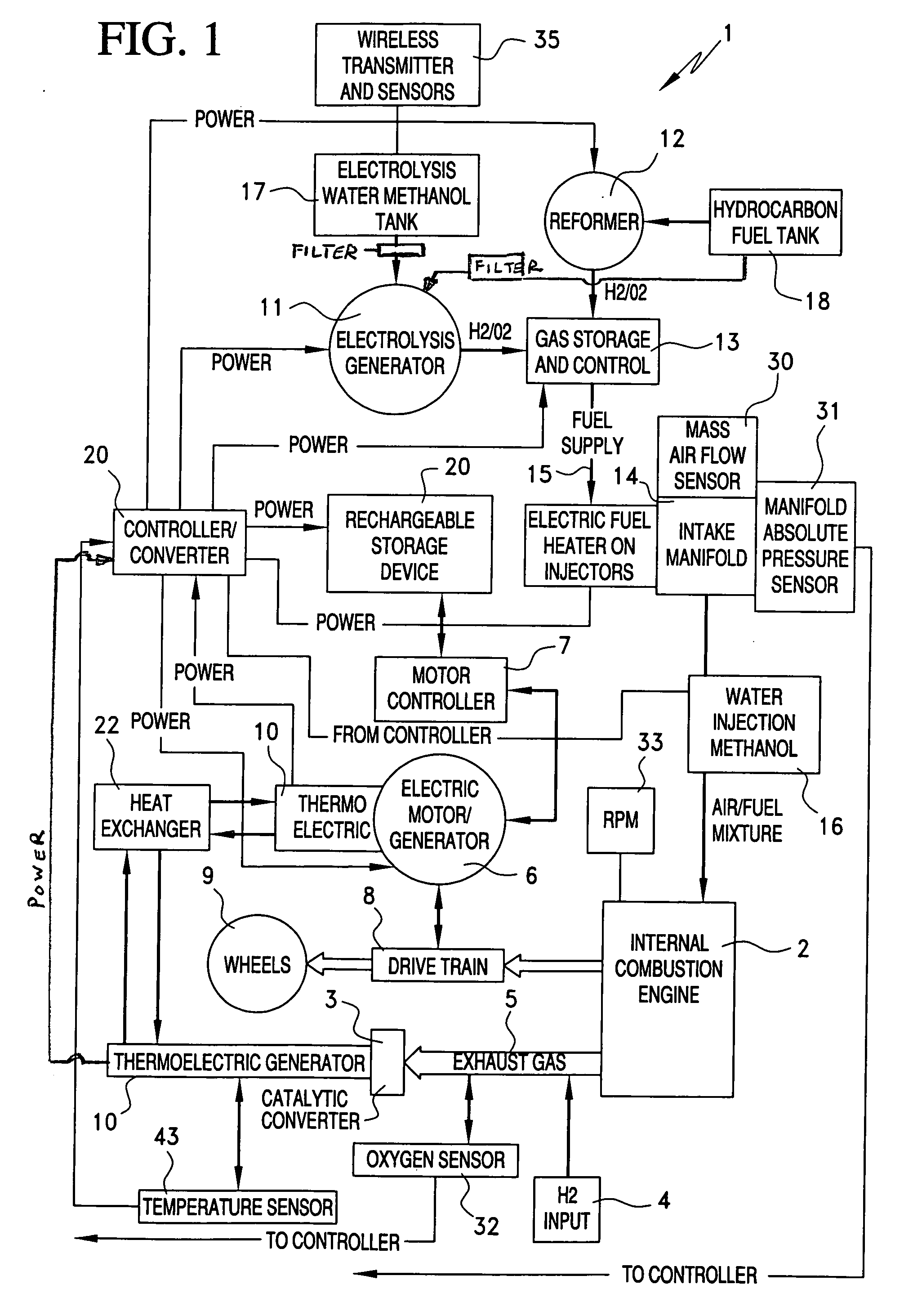
[0034]FIG. 1 shows a thermoelectric-hydrogen hybrid power system 1 that illustrates the principles of a preferred embodiment of the invention. Power system 1 includes an internal combustion engine 2 that generates an exhaust stream, and a catalytic converter 3 for reducing the amount of hydrocarbon pollutants in the exhaust stream by interaction with a catalyst. While power system 1 is especially suitable for vehicles having a drive train 8 and wheels 9, the invention may also be applied to other types of vehicles in which the exhaust stream might be directed through a catalytic converter, such as trains and watercraft, and it is also within the scope of the invention to apply the principles of the invention to a stationary generator system, or any other system that utilizes an internal combustion engine.

[0035] According to the principles of the invention, in order to reduce cold-start emissions by pre-heating the catalytic converter 3, power system 1 includes means, in the form of...


PUM


Abstract

Emissions from systems that use a catalytic converter are substantially reduced by introducing hydrogen, or a hydrogen containing fluid or fuel component, into the exhaust stream being scrubbed by the catalytic converter, resulting in instant lightoff and a significant reduction in emissions. Hydrogen for injection into the exhaust stream may, optionally, be generated within the vehicle using heat recovered from the catalytic converter, and/or the engine or elsewhere in the exhaust system, by a thermoelectric generator, the electrical output of which may be used to perform electrolysis and/or to power a reformer in order to generate the hydrogen. The thermoelectric generator may be retrofit onto the catalytic converter, or integrated in a way that enhances thermoelectric generation, including providing a catalyst coated heat sink and integrated cooling pipes to enhance the thermal differential required for thermoelectric generation. Sensors such as an oxygen sensor and temperature sensor may be provided to assess converter performance and adjust the temperature differential to ensure that the temperature of the converter remains optimum.

Description

BACKGROUND OF THE INVENTION [0001] 1. Field of the Invention [0002] This invention relates to a system for reducing vehicle emissions in a vehicle having an internal combustion engine and a catalytic converter, and in particular to a system and method for rapidly bringing the catalytic converter to light-off temperature by introducing a hydrogen containing fluid into the exhaust stream. [0003] The invention also relates to a system for reducing vehicle emissions by introducing a hydrogen containing fluid into the exhaust stream, and in which the hydrogen containing fluid is in the form of hydrogen gas generated by an on-board electrolysis device or reformer powered by the heat of the exhaust stream, for example by a thermo-electric generator secured to or integral with the catalytic converter. The hydrogen gas may also be added to the fuel intake to boost fuel efficiency and further reduce emissions. [0004] The invention further relates to a system for utilizing waste heat generated...

Claims


Application Information

Patent Timeline
Patent Type & Authority Applications(United States)
IPC IPC(8): F01N3/00
CPCF01N3/18F01N5/025F01N2610/04Y02T10/16Y02A50/20Y02T10/12
Inventor SULLIVAN, JOHN TIMOTHY
Owner SULLIVAN JOHN TIMOTHY
Why Eureka
Try Eureka