Electromagnetic actuator, fuel injection valve, method of controlling fuel injection valve, and method of driving the same

a technology of electric actuators and actuators, applied in the direction of electrical control, process and machine control, instruments, etc., can solve the problems of time-consuming and inability to read from the individual, and achieve the effect of easy reading and correction procedure in the program

Inactive Publication Date: 2006-08-17
HITACHI LTD
View PDF4 Cites 10 Cited by
  • Summary
  • Abstract
  • Description
  • Claims
  • Application Information

AI Technical Summary

Benefits of technology

[0029] An individual attestation code of the individual of the sensor or the electromagnetic actuator and operating characteristics can be read out easily by non-contact according to the present invention Therefore, the adjustment operation and the correction procedure in the program become easy.

Problems solved by technology

However, both an attestation code of the individual and specific data of the characteristic of the individual could not be read from the individual by non-contact in the above-mentioned prior art.
Therefore, there was a time-consuming problem in connection with the association work among the writing work of data to a storage element, the attestation of the individual and the specific data of the characteristic of the individual concerned.

Method used


Image

  • Electromagnetic actuator, fuel injection valve, method of controlling fuel injection valve, and method of driving the same
  • Electromagnetic actuator, fuel injection valve, method of controlling fuel injection valve, and method of driving the same
  • Electromagnetic actuator, fuel injection valve, method of controlling fuel injection valve, and method of driving the same

Examples


embodiment 1

[0074] (FIG. 1 and FIG. 2 . . . antifouling, waterproofs, guarantee of vibration resistance, and data entry is possible after assemble)

[0075] A first embodiment of the fuel injection valve according to the present invention is explained by using FIG. 1 and FIG. 2.

[0076] Configuration and basic operation of the fuel injection valve of the present invention are explained by using FIG. 1 in the beginning.

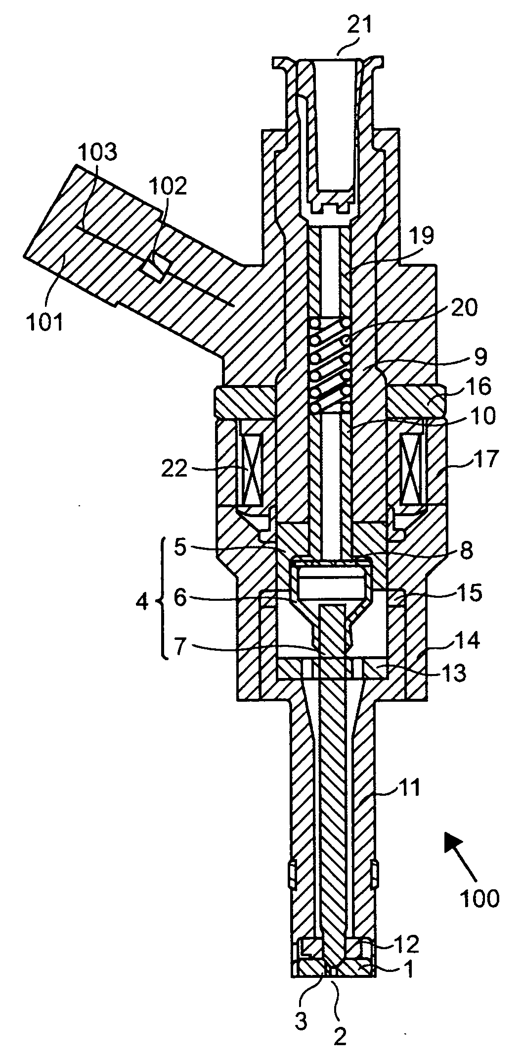
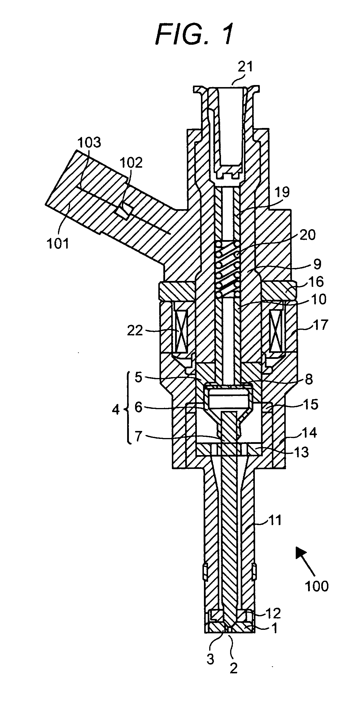
[0077]FIG. 1 is a sectional view showing a first embodiment of the fuel injection valve of the present invention.

[0078] Fuel injection hole 2 and valve seat 3 are provided to orifice plate 1. Orifice plate 1 is fixed at the point of nozzle holder 11 by a method of welding etc. Swirler 12 for turning the fuel is provided between orifice plate 1 and nozzle holder 11. Moreover, guide plate 13 is fixed inside of nozzle holder 11. Valve body 4 is slid and guided by the inside diameter part of swirler 12 and the hole provided at the center part of guide plate 13.

[0079] Valve body 4 is m...

embodiment 2

[0091] (FIG. 3 and FIG. 4 . . . it is possible to decrease an information amount and obtain fine information in the position where the variation is large.)

[0092] Next, a second embodiment of the fuel injection valve according to the present invention is explained by using FIG. 3 and FIG. 4.

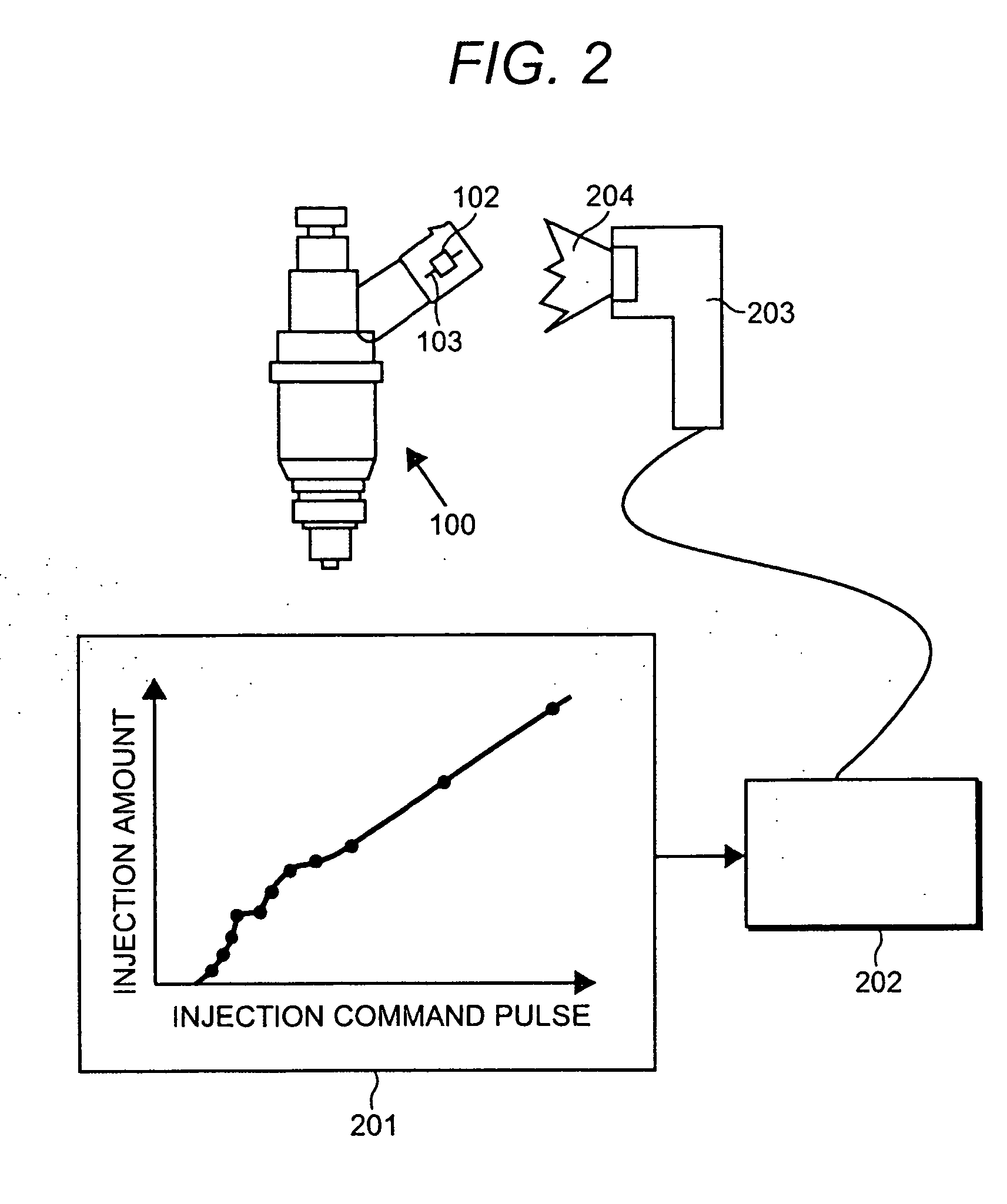
[0093]FIG. 3 is a diagrammatic view showing one example of the information input to above-mentioned information storage element 102.

[0094] The measurement value of a dynamic injection amount which is an injection amount when the fuel injection is performed by inputting the width of each injection command pulse in connection with an individual fuel injection valve is input to information storage element 102. It is desirable to divide the area of dynamic injection amount into small area 301, middle area 302 and large area 303, etc. as shown in FIG. 3. Further, how to divide is not limited to such three-division, but it is desirable to a plurality of areas. In small area 301 of the dynamic injecti...

embodiment 3

[0102] (FIG. 5, FIG. 6 and FIG. 7 . . . It is possible to expand the region where the minute injection amount can be controlled.)

[0103] Next, a third embodiment of the method of controlling the fuel injection valve according to the present invention is explained by using FIG. 5 to FIG. 7. FIG. 5 is a diagrammatic view showing the engine system configuration which uses one embodiment of the fuel injection valve of the present invention and the control method thereof.

[0104] Fuel injection valves 100a to 100d are installed in cylinders 502 to 505 of engine 501, respectively. Information reading parts 506 to 509 are provided in the neighborhood of fuel injection valves 100a to 100d. Information reading parts 506 to 509 are connected with engine control unit 511 through signal wire 510.

[0105] It is possible to prevent the adverse effect due to noise, etc. in the engine room when the information is read by providing information reading parts 506 to 509 in the neighborhood of fuel injec...


PUM


Abstract

Information storage element 102 and transmitter-receiver 103 are molded in resin connector part 101 of fuel injection valve 100 which projects outside of the engine by molding. The precise control of an injection amount is enabled by using directly the characteristic of injection amount stored in information storage element 102, and obtaining the width of the injection command pulse corresponding to the injection amount instruction value. Thereby, the minimum injection amount which is the minimum value of the fuel supply amount which can be controlled is reduced.

Description

BACKGROUND OF THE INVENTION [0001] The present invention relates to a sensor for measuring various physical values, and an electromagnetic actuator for adjusting various physical values, more concretely to a motor-driven throttle valve device installed for instance in an internal combustion engine or a compression ignition oil engine, an AFS (Airflow sensor) which detects the flow rate, a throttle valve position sensor which detects the rotating angle degree of the valve, a fuel injection valve which controls the amount of fuel supply, a high-pressure pump which supplies fuel to the fuel injection valve, a motor for an electric automobile, or a rotation sensor (Popular name: a resolver) which detects the rotation of a motor by detecting the position of a magnetic pole of a rotator of the motor concerned, and further to a control method or a driving method. [0002] In general, so-called ID tags or ID tag systems are known, where a storage element storing the attestation code for artic...

Claims


Application Information

Patent Timeline
Patent Type & Authority Applications(United States)
IPC IPC(8): F02B3/00F02M51/00
CPCF02D11/106F02D41/2419F02D41/2435F02D41/2464F02D41/2467F02D41/247F02D2250/16F02M51/061F02M61/16F02M65/00F02M2200/24
Inventor MAEKAWA, NORIYUKIABE, MOTOYUKITOKUO, KENICHIROKOWATARI, TAKEHIKOISHIKAWA, TOHRUINNAMI, TOSHIYUKIHANAWA, KAZUHIKOSHIMADA, SATOSHI
Owner HITACHI LTD
Why Eureka
Try Eureka