Optical transmitter with integrated amplifier and pre-distortion circuit

a technology of optical transmitter and amplifier, applied in the field of optical transmitter, can solve the problems of increasing the power dissipation of prior art transmitters, increasing the supply voltage of laser drivers, and consuming a substantial amount of power, so as to reduce the product of second and higher order distortion

Inactive Publication Date: 2006-08-17
EMCORE INC
View PDF6 Cites 107 Cited by
  • Summary
  • Abstract
  • Description
  • Claims
  • Application Information

AI Technical Summary

Benefits of technology

[0020] It is another object of the present to provide an improved optical transmitter using a modular, packaged laser and amplifier subassembly with a compact size and low power dissipation.
[0022] It is another object of the present invention to provide an optical transmitter for use in an optical transmission system with a TEC cooler in the laser package for stabilizing the temperature of both the laser and the intermediate circuitry.
[0026] The present invention further provides a packaged laser including a predistortion circuit for reducing second and higher order distortion products produced by the nonlinear operation of the laser.

Problems solved by technology

Such large voltage swings require increased laser driver supply voltages and increase overall system power dissipation.
As a result, such prior art transmitters are relatively large and consume a substantial amount of power, typically over ten watts.
In addition, another drawback of prior art modules is that the discrete components of typical analog transmitters are interconnected by transmission lines typically in the form of microstrips.
However the use of impedance matching resistors shunted to ground between electrical components further increases the power dissipation and transmitter heat load in the laser module.
In addition, the integration of the discrete RF circuits and the laser module on the PCB typically results in relatively large transmitters with relatively high cost and low density.
The amplifier used in prior art optical transmitters, such as the Anadigics ACA2304 integrated circuit, dissipates a substantial amount of heat (around six watts) and takes up a large amount of space on the printed circuit board.
Another issue is that the amplifier is typically spaced from the laser diode by several inches, and therefore such design requires some form of impedence matching circuitry (for example, a transformer) be used between the amplifier circuit and the laser diode.
Thus, although it is desirable to reduce the size and power requirements of optical transmitters for analog RF applications, prior to the present invention it has not been possible to implement an amplifier integrated circuit inside a laser package because of the relatively large size of the integrated circuit and its associated power requirements and heat dissipation issues.
However, the method suffers from crudeness because nonlinear devices frequently have amplitude and phase distortion characteristics dependent on the frequency of the modulating signal.
Neglecting to correct for the frequency dependence of the distortion leads to a result which may be quite tolerable for many systems and for signals with relatively narrow bandwidth.
However, they become particularly troublesome when converting an electrical TV signal to an optical signal for cable transmission.
Although multi-path distortion circuits can be used in a broad variety of applications, the design of these circuits is relatively complex.
This complexity manifests itself in circuits that are often too expensive for applications needing only a modest degree of linearization.
Many non-linear transmitters or amplifiers, however, contain reactive elements such as inductance capacitances or delays, which cause the device to produce distortion depending on the input and output frequencies and the distortion frequencies.
However, the circuit disclosed by Nazarthy may not have the right phase or frequency dependence for each set of input frequencies to be substantially the same in magnitude and opposite in sign to the distortion produced by the non-linear device.

Method used


Image

  • Optical transmitter with integrated amplifier and pre-distortion circuit
  • Optical transmitter with integrated amplifier and pre-distortion circuit
  • Optical transmitter with integrated amplifier and pre-distortion circuit

Examples


Embodiment Construction

[0043] Details of the present invention will now be described, including exemplary aspects and embodiments thereof. Referring to the drawings and the following description, like reference numbers are used to identify like or functionally similar elements, and are intended to illustrate major features of exemplary embodiments in a highly simplified diagrammatic manner. Moreover, the drawings are not intended to depict every feature of actual embodiments or the relative dimensions of the depicted elements, and are not drawn to scale.

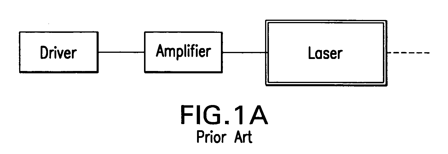
[0044]FIG. 1A is a highly simplified block diagram of an optical transmitter in a first exemplary embodiment in accordance with the prior art in which a driver and amplifier are external to the laser module.

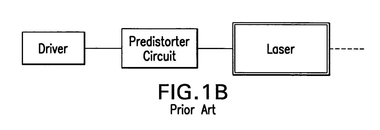
[0045]FIG. 1B is a highly simplified block diagram of an optical transmitter in a second exemplary embodiment in accordance with the prior art in which a driver and pre-distorter circuits are external to the laser module.

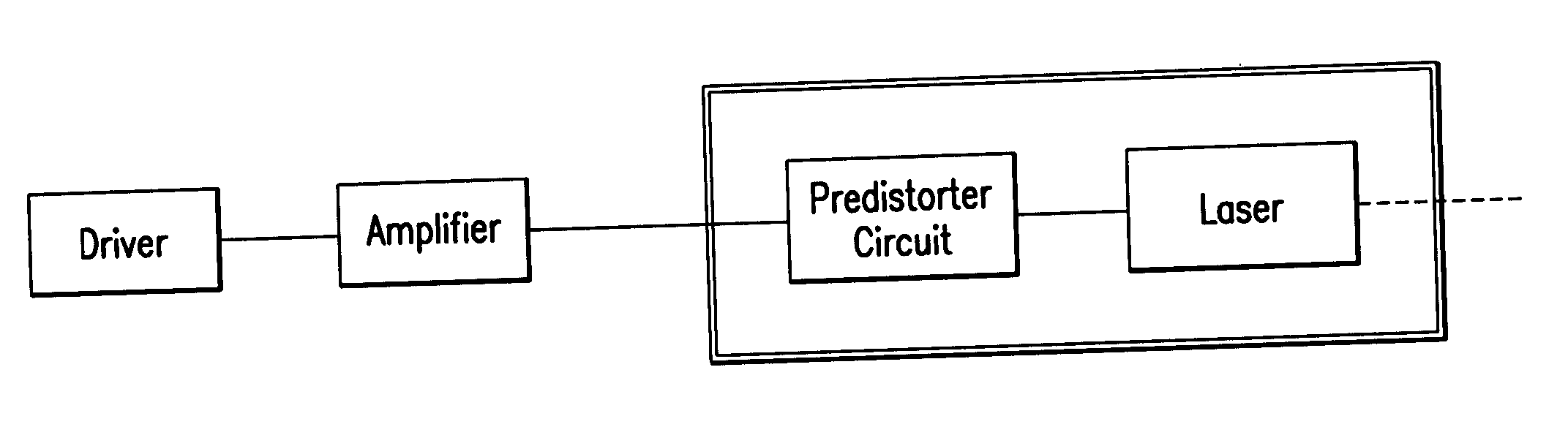
[0046]FIG. 2 is a highly simp...


PUM


Abstract

An optical transmitter including a housing containing an electrical input disposed in said housing for receiving an information signal; an amplifier for electronically amplifying the input signal; and a laser connected to the output of the amplifier for generating a modulated light beam corresponding to the information signal that is emitted externally from said housing.

Description

REFERENCE TO RELATED APPLICATIONS [0001] This application is related to copending U.S. patent application Ser. No. filed Jan. ______, 2005, of Rongsheng Miao et al. entitled “Coaxial Cooled Laser Modules with Integrated Thermal Electric Cooler and Optical Components” and assigned to the common assignee.BACKGROUND OF THE INVENTION [0002] 1. Field of the Invention [0003] The invention relates to optical transmitters and, in particular to packaged assemblies or hermetically sealed modules that provide a communications interface between a computer or communications unit having an analog or digital electrical output signal and an optical fiber, such as used in fiber optic communications system. [0004] 2. Description of the Related Art [0005] A variety of optical transmitters are known in the art which include a modulator circuit that converts an analog or digital electrical signal from a computer or communications unit into a modulated current that is applied to a semiconductor laser mod...

Claims


Application Information

Patent Timeline
Patent Type & Authority Applications(United States)
IPC IPC(8): H04B10/04H04B10/43
CPCH04B10/58H04B10/50
Inventor IANNELLI, JOHNLU, ALBERT
Owner EMCORE INC
Why Eureka
Try Eureka