Method and arrangement for x-ray examination

a technology of x-ray and arrangement, which is applied in the direction of instruments, catheters, applications, etc., can solve the problems of inability to safely navigate the catheter, the catheter position cannot be uniquely determined, and the use of magnetic navigation is limited, so as to achieve easy calculation and control

Inactive Publication Date: 2006-08-17
SIEMENS AG
View PDF5 Cites 4 Cited by
  • Summary
  • Abstract
  • Description
  • Claims
  • Application Information

AI Technical Summary

Benefits of technology

[0007] This change at the location of the x-ray tube can be compensated for through the opposing magnetic field controlled in accordance with the change in the foreign magnetic field, so that the image sections of x-ray images recorded at different times still cover the same area, despite a change in the foreign magnetic field which temporarily has to be taken into account. In the above-mentioned x-ray examination method provided for optical checking of the navigation of a catheter, the invention makes possible a fluoroscopy image covering the same area during the entire examination as an x-ray image created before the navigation, especially by means of digital subtraction angiography, so that the position of the catheter can be easily detected despite the foreign magnetic field necessary for navigation and thus the catheter can be safely navigated. The inventive solution expands the area of application of magnetic navigation to x-ray examination methods in which, especially with the aid of digital subtraction angiography an x-ray image is initially created to which further x-ray images of the same image section created during magnetic navigation are related.
[0013] In a further embodiment of the invention at least one permanent magnet advantageous as regards low technical outlay or low cost is provided as the compensating magnet. The magnetic field alignment of the at least one permanent magnet can be varied by a spatial rotation of its position.
[0017] Furthermore it is advantageous to provide an even number of compensation magnets arranged symmetrically in pairs in each case on opposing sides of the x-ray tube. In this arrangement of the compensation magnets the two, especially similar compensation magnets of each pair have are at the same distance from the x-ray tube and have the same or symmetrically mirrored spatial orientation so that an opposing magnetic field component generated in each case by the relevant pair is easy to calculate because of its symmetry and / or homogeneity at the location of the x-ray tube and the entire opposing magnetic field is thus easily able to be controlled. A technically especially simple further embodiment is represented here by the use of only two compensation magnets.

Problems solved by technology

The change in the magnetic field du ring navigation causes the fluoroscopy x-ray images to shift relative to the original x-ray image created by means of digital subtraction angiography so that the two image sections of the x-ray images no longer coincide, the position of the catheter can no longer be uniquely determined and a safe navigation of the catheter is not possible.
Thus the use of magnetic navigation is limited to medical specialist areas in which it is possible to dispense with an x-ray image created prior to navigation, especially one created by means of digital subtraction angiography.

Method used


Image

  • Method and arrangement for x-ray examination
  • Method and arrangement for x-ray examination
  • Method and arrangement for x-ray examination

Examples


Embodiment Construction

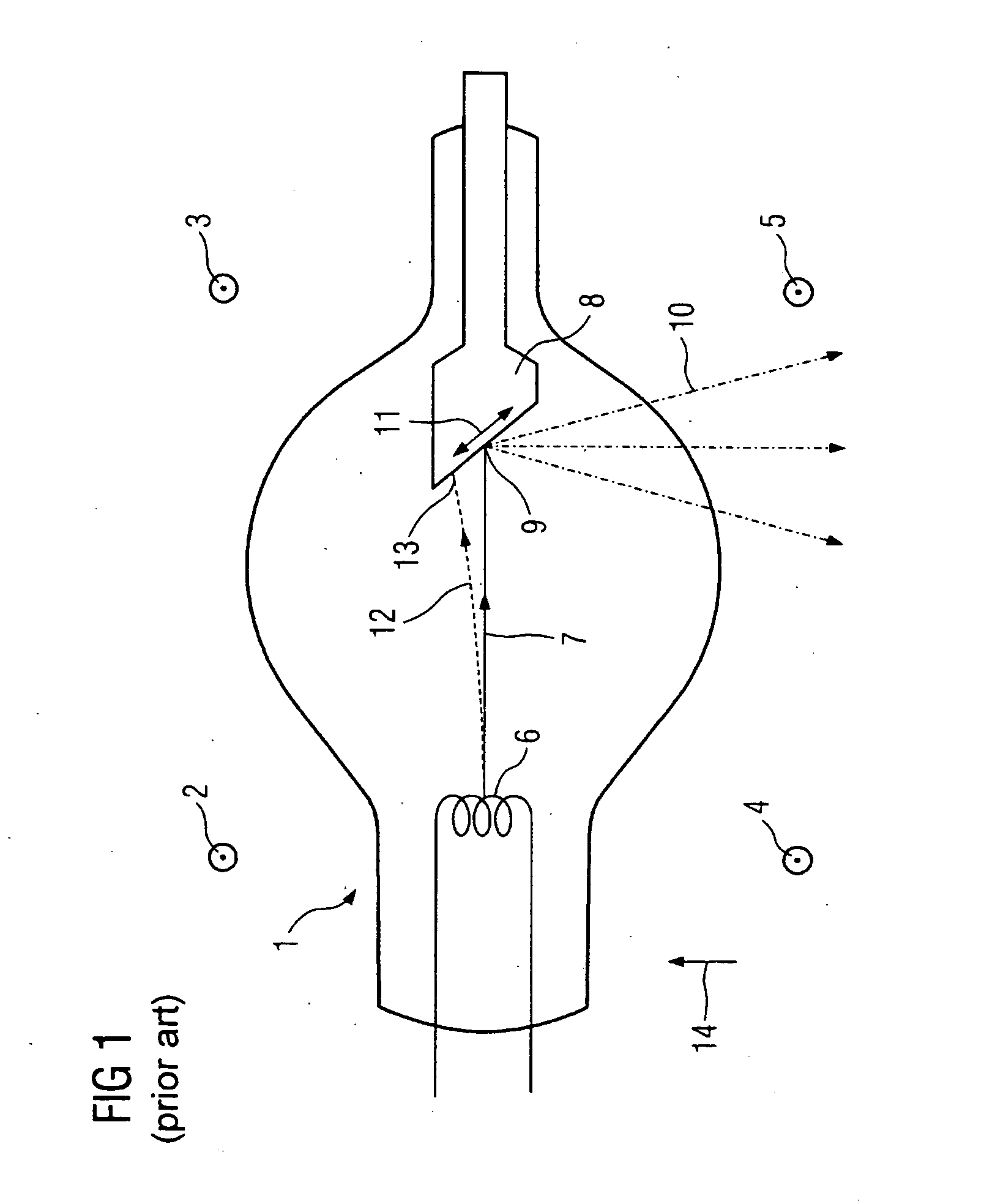
[0023]FIG. 1 shows the layout of an x-ray tube 1 known per say in accordance with the prior art in a variable foreign magnetic field essentially arranged at right angles to the plane of the diagram, which is represented by four magnetic field vectors 2-5 passing through the plane of the diagram and an operational function of the x-ray tube provided at two different points in time. At the first point in time the foreign magnetic field at the location of the x-ray tube is negligibly small so that an electron beam emitted from a cathode 6 of the x-ray tube 1 travels to an anode 8 on an essentially straight line path 7 represented by a solid line contour. The target area 9 of the electron beam on the anode 8 which is essentially in the form of a point is a source of x-ray radiation 10 and is designated as the focus.

[0024] A change in the magnetic field strength of the foreign magnetic field 2-5 causes the focus of the x-ray radiation 10 to shift on the anode in the direction of movemen...


PUM


Abstract

In order during an x-ray examination, despite a variable foreign magnetic field at the location of an x-ray tube to still enable x-ray images with image sections giving the same coverage to be generated, there is provision in accordance with the invention to compensate for the previously determined change to the foreign magnetic field at the location of the x-ray tube by a correspondingly controlled opposing magnetic field; Advantageously at least one compensating magnet is provided for this purpose which can be assigned to the x-ray tube and is controllable by a processing unit depending on this change.

Description

CROSS REFERENCE TO RELATED APPLICATIONS [0001] This application claims priority to the German application No. 10 2005 002 191.3, filed Jan. 17, 2005 which is incorporated by reference herein in its entirety. FIELD OF INVENTION [0002] The invention relates to a method or an arrangement for x-ray examination with an x-ray tube in a variable foreign magnetic field, especially for extracorporeal magnetic navigation of an intracorporeal catheter. BACKGROUND OF INVENTION [0003] During an x-ray examination electrons in the form of an electron beam are accelerated in an x-ray tube towards an anode and form a focus there which represents the source of the x-ray radiation, In a magnetic navigation of a catheter in blood vessels or in the heart of a patient or a laboratory animal known from DE 103 13 868 A, such an x-ray tube is operated during the x-ray examination in the variable foreign magnetic field necessary for navigation; In this way the electron beam is deflected by the foreign magnet...

Claims


Application Information

Patent Timeline
Patent Type & Authority Applications(United States)
IPC IPC(8): A61M25/00
CPCA61B6/12A61M25/0127G01N23/04A61B6/4021
Inventor KLEEN, MARTIN
Owner SIEMENS AG
Why Eureka
Try Eureka