Rigid patient support element for low patient skin damage when used in a radiation therapy environment

a patient support and radiation therapy technology, applied in the direction of patient positioning for diagnostics, applications, furniture parts, etc., can solve the problems of high skin dose and skin damage of patients, inability to provide the precise positioning required for state of the art treatment techniques, and inability to meet patient support surfaces and devices. to achieve the effect of reducing skin burns and skin damag

Inactive Publication Date: 2006-08-24
QFIX SYSTEM LLC
View PDF9 Cites 25 Cited by
  • Summary
  • Abstract
  • Description
  • Claims
  • Application Information

AI Technical Summary

Benefits of technology

[0009] Another embodiment of the invention provides a method for reducing skin burn comprising the steps of providing a patient support surface; placing a rigid patient support element of the present invention on the patient support surface; placing a patient on the rigid patient support element; directing a high energy radiation beam through the patient support surface and the rigid patient support element into the patient; and reducing skin damage by diffusing the electrons generated by Compton scattering in the patient support surface.

Problems solved by technology

It is these scattered electrons that strike a patient during treatment with x-radiation resulting in high skin dose and damage to the patient's skin
This generally performs well from the standpoint of patient surface dosage but is impractical for many patient support surfaces and devices.
In addition, it does not provide the precise positioning required for state of the art treatment techniques such as Inter-Modulated Radiation Therapy (IMRT) and Image Guided Radiation Therapy (IGRT).
However, the dosage that occurs at the contact point between the patient and support surface can be high.
Some of this electron energy is directed at the patient and because electrons travel a relatively short distance, a large dose of electron energy may be deposited in the patients skin, causing serious skin damage.
Current solutions are either rigid but produce an undesirable amount of electrons or are not adequately rigid but reduce electron generation.

Method used


Image

  • Rigid patient support element for low patient skin damage when used in a radiation therapy environment
  • Rigid patient support element for low patient skin damage when used in a radiation therapy environment
  • Rigid patient support element for low patient skin damage when used in a radiation therapy environment

Examples


Embodiment Construction

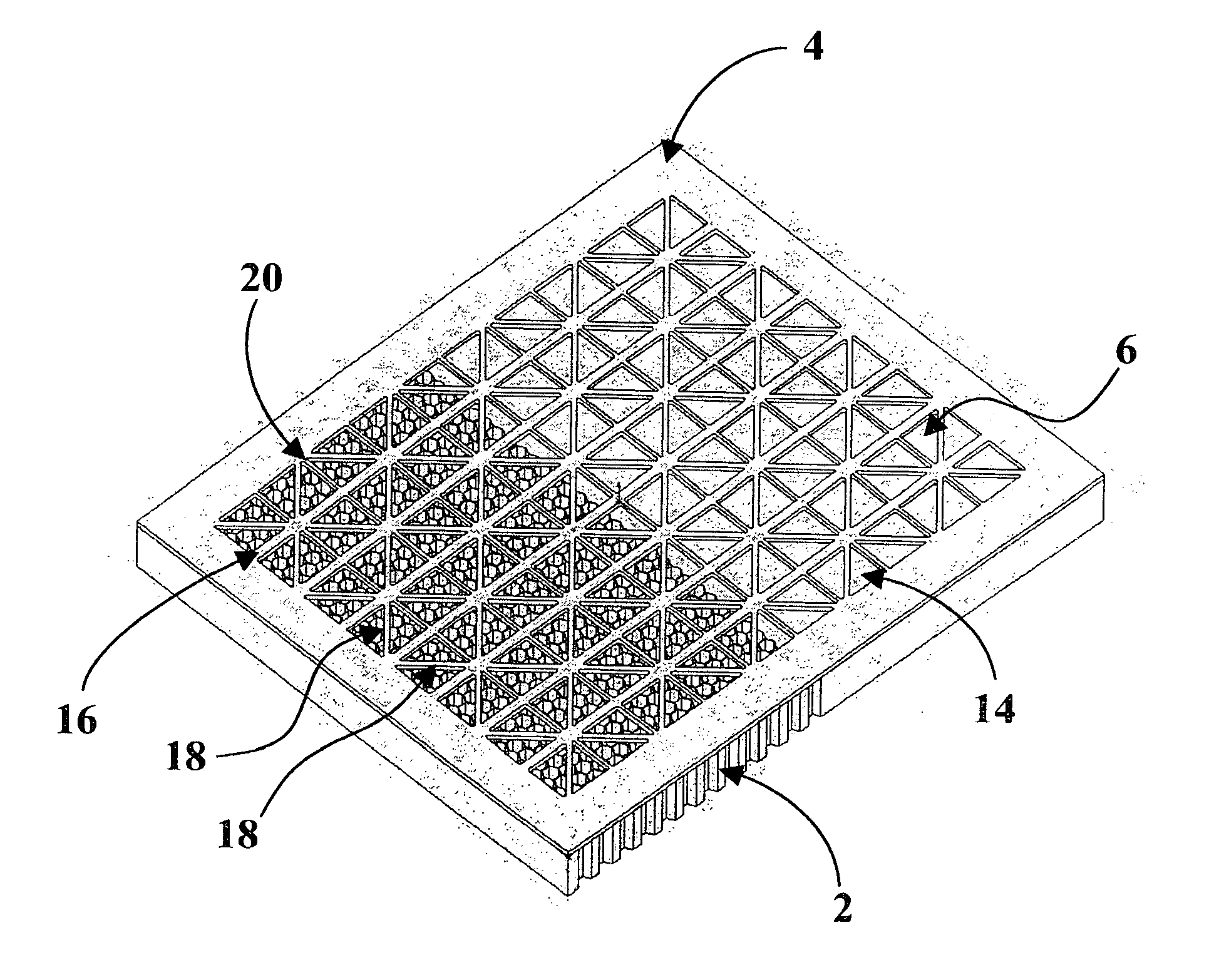
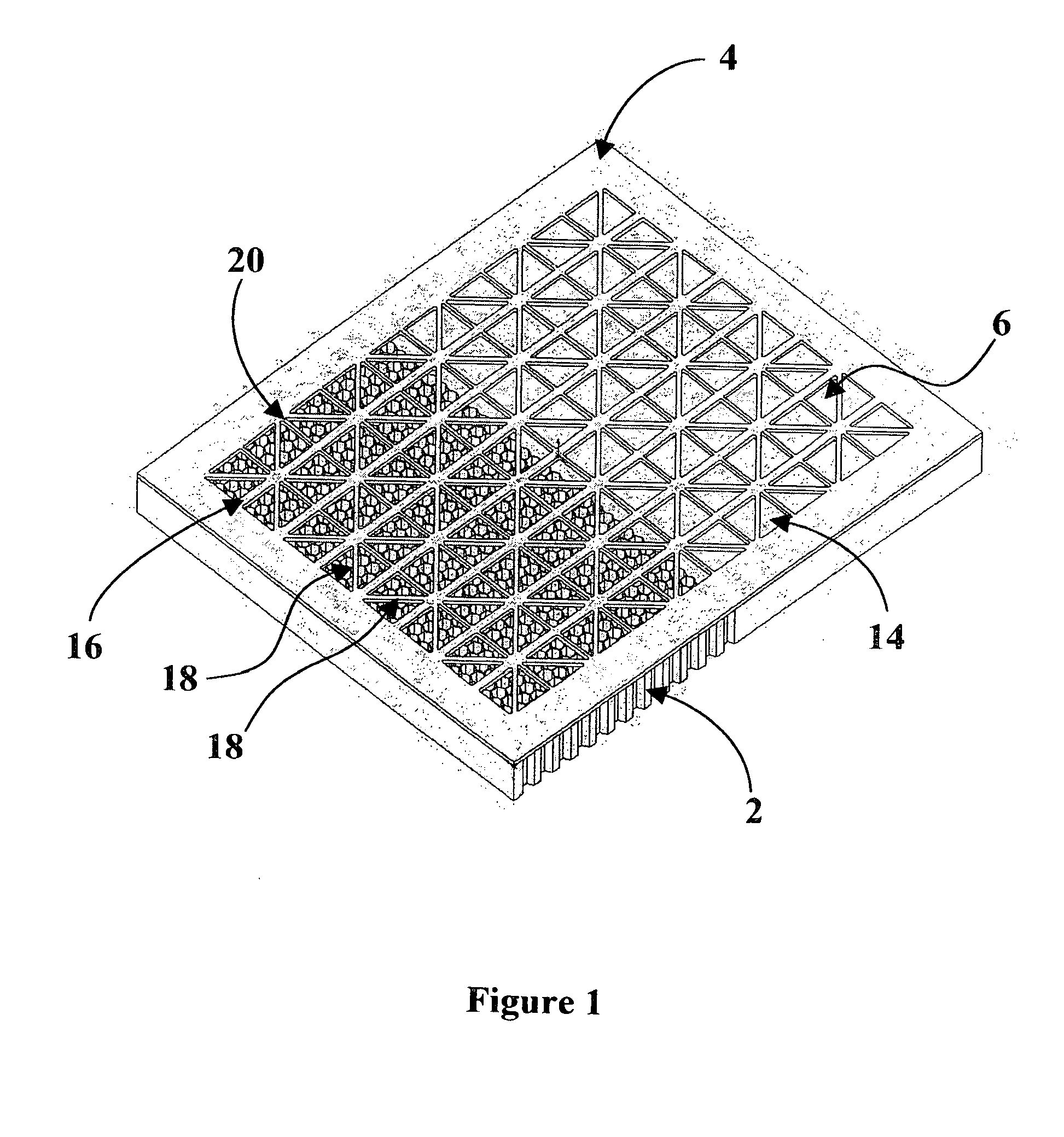
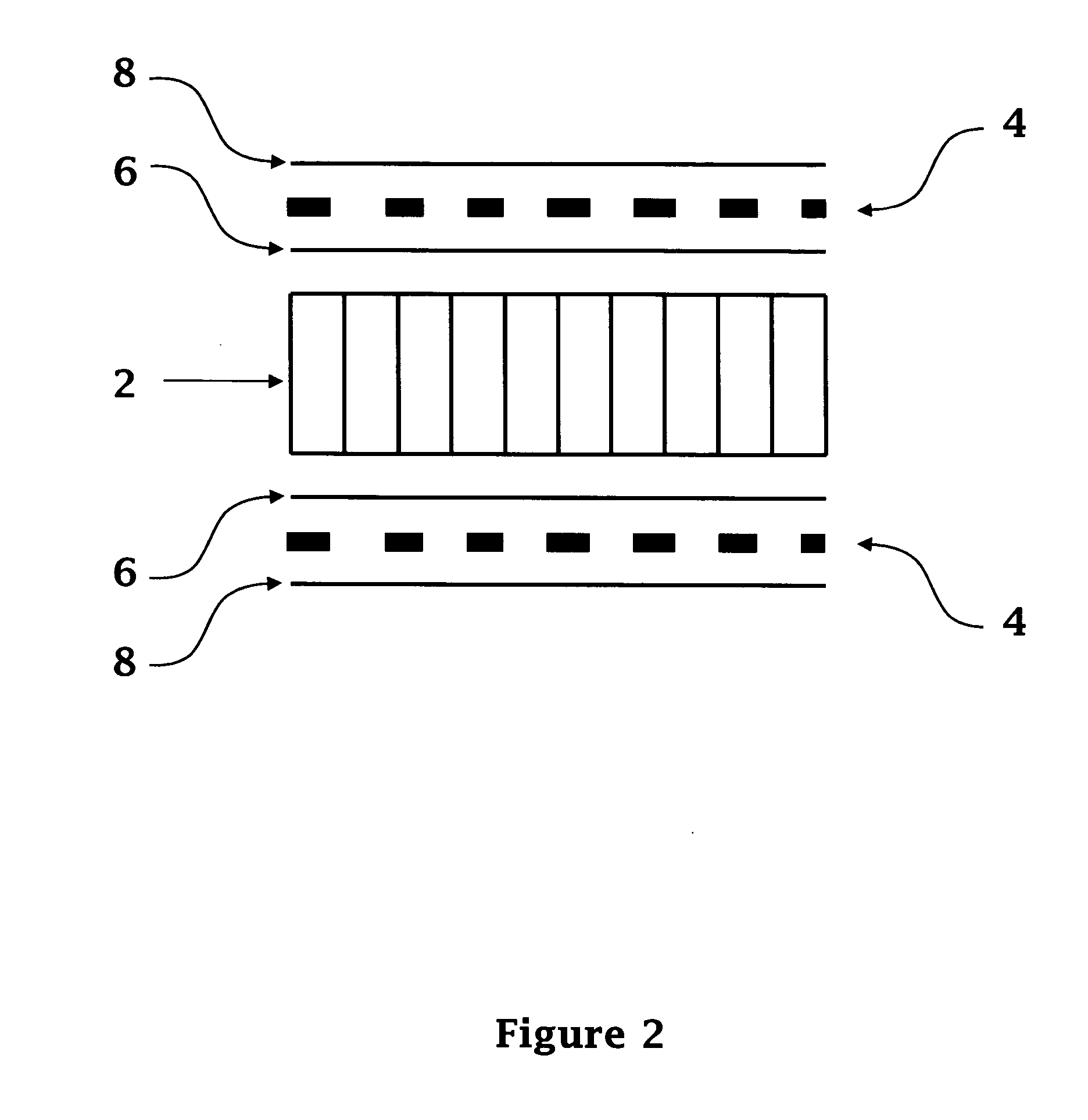
[0024] Currently, the two most common constructions for Radiation Therapy (RT) patient tables and devices are; (1) continuous solid carbon fiber face sheets on a rigid foam core, and (2) a carbon fiber grid. The grid is generally produced from a flat sheet of carbon fiber (between 0.040″ and 0.250″ think) through which a repeating pattern of square or round holes is cut. The grid provides superior performance when compared to a rigid foam core construction because it produces less electron scattering. However, the grid systems are much less stiff than the rigid foam systems.

[0025] The invention described allows structures with electron generation comparable to a grid to be built but at an order of magnitude higher stiffness than a grid system. The invention can provide stiffness comparable to a rigid foam structure. FIG. 3 illustrates the dose versus depth curve for a one inch and three inch sample of the present invention compared with a sample with structural integrity of a compl...


PUM


Abstract

A rigid patient support element that is substantially transparent to high energy x-radiation comprising a structural core and one or more perforated face sheets attached to at least one of the top side or bottom side of the element. The support element reduces Compton scattering thereby reducing patient skin damage. The support element of the present invention can be integrated into a patient support surface, used as an insert or used as a spacer and easily removable from a patient support surface.

Description

CROSS-REFERENCE TO RELATED APPLICATIONS [0001] This application claims the benefit of provisional application 60 / 650,859 filed Feb. 8, 2005 and 60 / 682,321 filed May 18, 2005.BACKGROUND OF THE INVENTION [0002] Patients are commonly exposed to x-radiation from 1 MV to 50 MV during modern medical treatment and diagnostic procedures. X-rays are electromagnetic waves composed of photons. During treatment, a patient is often lying on a rigid support surface that is composed of carbon composite materials. When an x-radiation photon strikes an electron contained in the support surface, the photon scatters in one direction while the electron scatters in another direction. The effect is similar to the collision of two billiard balls on a pool table and is known as Compton scattering. It is these scattered electrons that strike a patient during treatment with x-radiation resulting in high skin dose and damage to the patient's skin [0003] Traditional patient support devices used in radiation th...

Claims


Application Information

Patent Timeline
Patent Type & Authority Applications(United States)
IPC IPC(8): A61B6/04A61G13/12
CPCA61B6/0442A61N5/10A61G2210/50
Inventor COPPENS, DANIEL D.KIRK, JOHN DAMONRABENO, DAVID M.WINWARD, THOMAS RYAN
Owner QFIX SYSTEM LLC
Why Eureka
Try Eureka