Method of applying mercury reagent with coal

a technology of mercury reagent and coal, which is applied in the field of combustion of fossil fuels, can solve the problems of relatively ineffective current scrubber technology for removing elemental mercury from flue gas, and achieve the effect of substantial economic savings and low mercury emissions

Inactive Publication Date: 2006-08-24
THE BABCOCK & WILCOX CO
View PDF2 Cites 87 Cited by
  • Summary
  • Abstract
  • Description
  • Claims
  • Application Information

AI Technical Summary

Benefits of technology

[0011] The present invention, due to its ease of incorporation and benefit in mercury removal, provides an important advantage over prior art methods due to unexpected advantages and cost savings associated with forgoing the need to install expensive mercury vapor removal means in order to lower mercury emiss

Problems solved by technology

Flue gas scrubbers are readily able to remove a substantial portion of mercury in the oxidized form, ho

Method used


Image

  • Method of applying mercury reagent with coal

Examples


Embodiment Construction

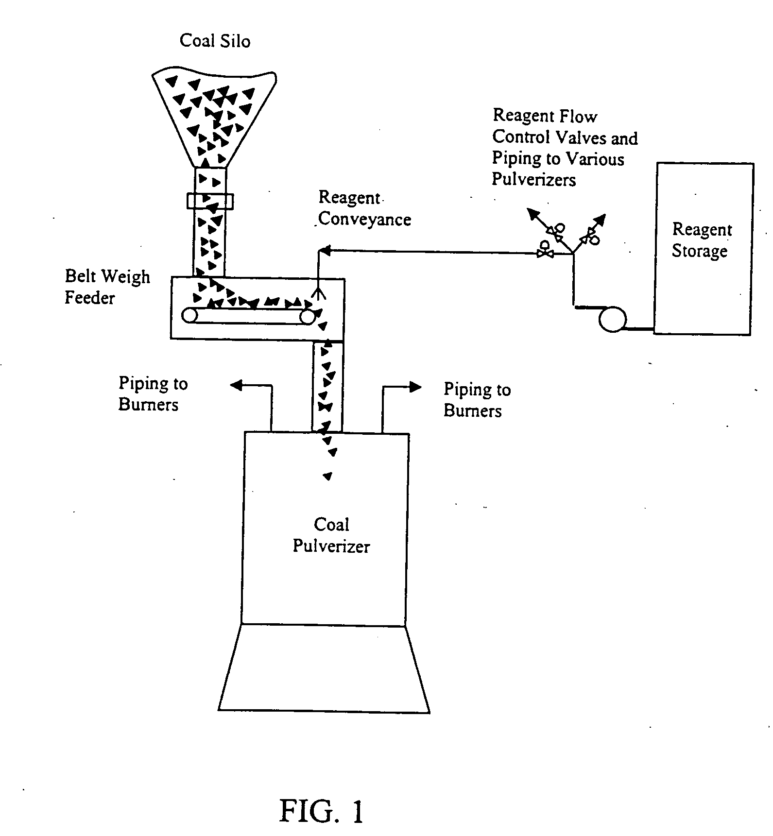
[0013] Referring now to FIG. 1, a schematic diagram of an embodiment of the present invention is shown. A fossil fuel, such as coal, is provided from a coal silo onto a belt feeder, such as a gravimetric feeder or other belt feeding apparatus. The belt feeder in turn provides the coal to the pulverizer wherein the coal is pulverized to a predetermined particle size.

[0014] Prior to being pulverized, preferably while the coal is on the belt feeder or alternatively dropping into the pulverizer, the coal is treated with a liquid or solid chlorine reagent, preferably sodium chloride or calcium chloride. Spray nozzles located above and / or around the belt may be provided to treat the coal with liquid chlorine reagent prior to pulverization. Reagent flow rate may be control manually by valves or alternatively utilize automated means. Alternatively, reagent may be supplied to coal in the form of solid pellets, powder, or granules utilizing a solids feeder in place of the spray nozzle. Prefe...


PUM


Abstract

A method of halogenating coal prior to combustion, wherein the coal is treated with a halogen prior to pulverization and the pulverized halogenated coal is delivered to a burner as fuel for a combustion process.

Description

FIELD AND BACKGROUND OF THE INVENTION [0001] The present invention generally relates to combustion of fossil fuels in a boiler or furnace, and more specifically to a method of halogenating a fossil fuel prior to combustion to enhance removal of mercury from flue gas. [0002] Coal fired utility plants are necessary to satisfy the energy needs of many countries. Heat energy derived from combusting fossil fuels such as coal produces steam utilized to drive energy producing turbines. A byproduct of the combustion process is a flue or combustion gas which, after a cleaning process, exits into the atmosphere. [0003] Fossil fuels such as coal may contain varying levels of mercury. Upon combustion mercury may enter the flue gas as a solid particulate or as a gas in the vapor phase as elemental mercury or in one of many oxidized forms. Flue gas scrubbers are readily able to remove a substantial portion of mercury in the oxidized form, however current scrubber technology is relatively ineffect...

Claims


Application Information

Patent Timeline
IPC IPC(8): C10L5/00
CPCC10L5/366C10L9/10
Inventor MCDONALD, DENNIS K.EVANS, AMY P.JANKURA, BRYAN J.
Owner THE BABCOCK & WILCOX CO
Why Eureka
Try Eureka