Silicon gas injector and method of making

Inactive Publication Date: 2006-08-24
INTEGRATED MATERIALS
View PDF10 Cites 234 Cited by
  • Summary
  • Abstract
  • Description
  • Claims
  • Application Information

AI Technical Summary

Problems solved by technology

However, the open bottom end of the bell jar 18 and the mechanical support of the pedestal 22 cause the lower end of the furnace to have a lower temperature, often low enough that the process such as chemical vapor depositio

Method used


Image

  • Silicon gas injector and method of making
  • Silicon gas injector and method of making
  • Silicon gas injector and method of making

Examples


Embodiment Construction

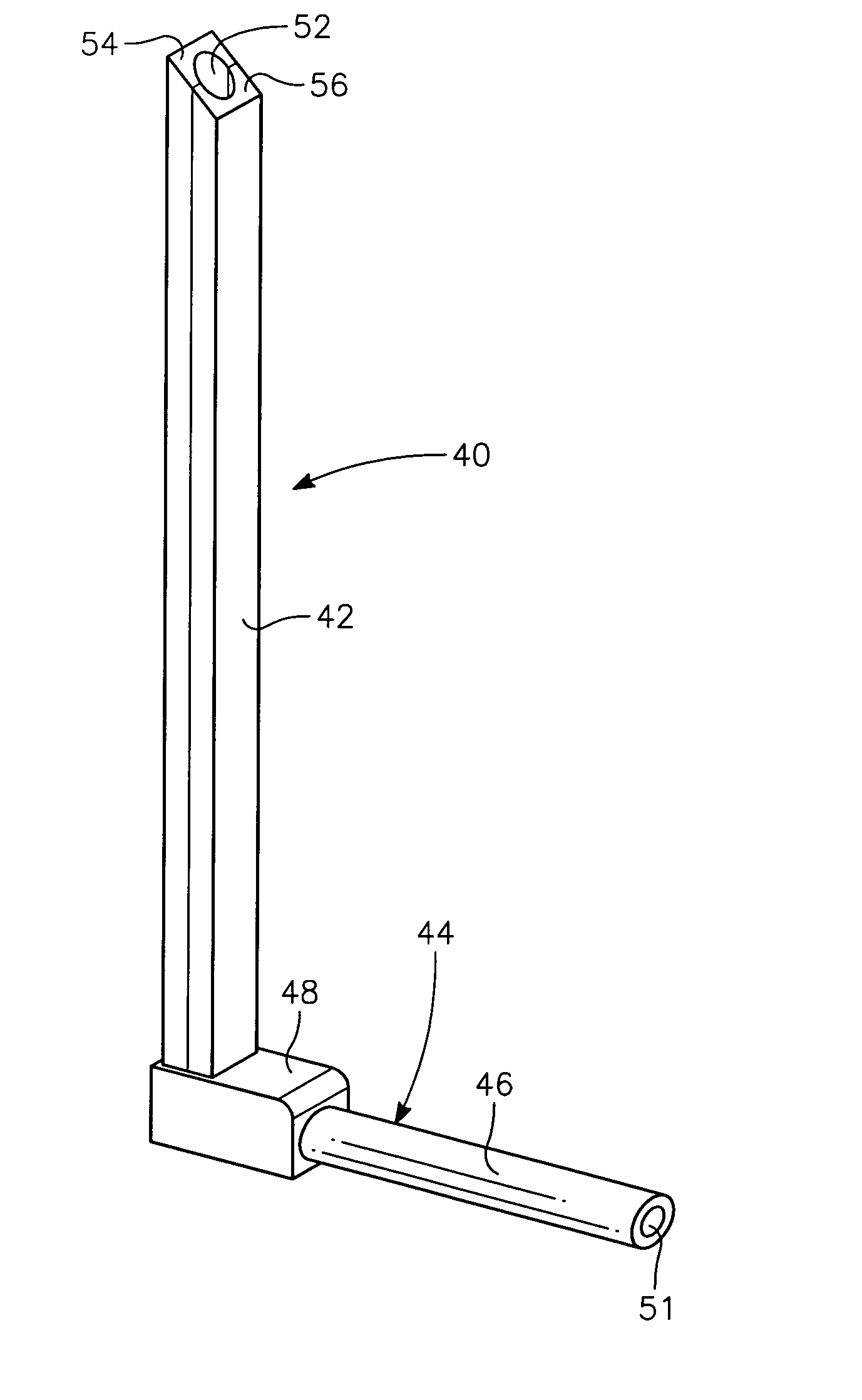
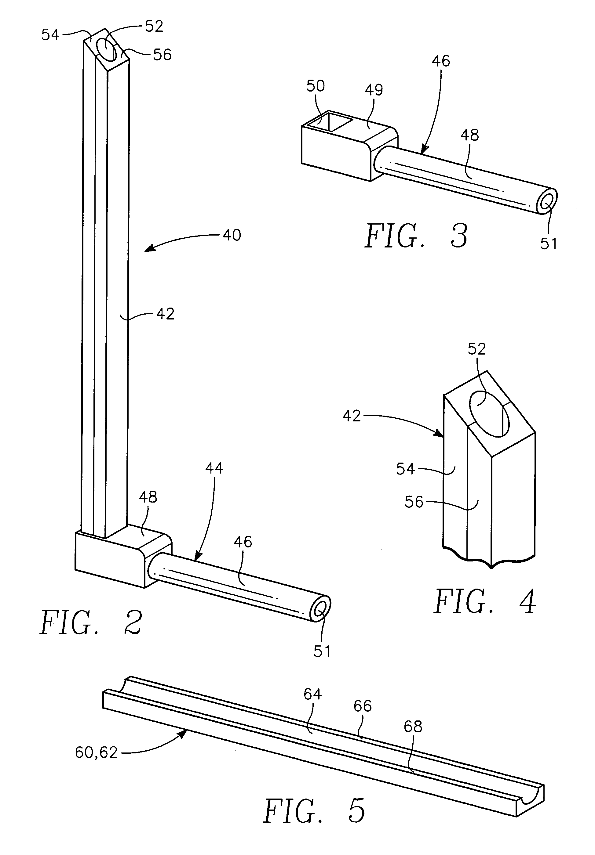
[0022] One embodiment of an injector 40 of the invention illustrated in the orthographic view of FIG. 1 includes an injector straw 42 (also referred to as a tube) and a knuckle 44 (also known as a connector). The knuckle 46, illustrated in more detail in the orthographic view of FIG. 3, includes a supply tube 48 and an elbow 49 having a recess 50 to receive the injector straw 42. The supply tube 48 may have an outer diameter of approximately 4 to 8 mm with a correspondingly sized inner circular bore 51.

[0023] The end of the supply tube 48 may be connected through a vacuum fitting and O-ring to a gas supply line supplying the desired gas or gas mixture into the furnace, for example, ammonia and silane for the CVD deposition of silicon nitride. The entire integral knuckle 46 may be machined from annealed virgin polysilicon according to the process described by Boyle et al. in U.S. Pat. No. 6,450,346. The machining includes connecting the supply bore 51 to the recess 20. Alternatively...


PUM

PropertyMeasurementUnit
Size distributionaaaaaaaaaa
Temperatureaaaaaaaaaa

Abstract

A gas injector tube usable in a batch thermal treatment oven including two silicon shells joined together with an adhesive formed of a fine silicon powder and a curable silica-forming agent, such as a spin-on glass, which is ultrasonically homogenized. The tube may have a gas outlet on its distal end or be sealed with a silicon cap and have side outlet holes formed along its side. The silicon injector tube may be used in combination with a silicon tower and a silicon liner so that all bulk parts within the furnace hot zone are formed of silicon.

Description

RELATED APPLICATION [0001] This application claims benefit of provisional application 60 / 655,483, filed Feb. 23, 2005.FIELD OF THE INVENTION [0002] The invention relates generally to thermal processing of semiconductor wafers. In particular, the invention relates to gas injectors in a thermal treatment furnace. BACKGROUND ART [0003] Batch thermal processing continues to be used for several stages in the fabrication of silicon integrated circuits. One low temperature thermal process deposits a layer of silicon nitride by chemical vapor deposition, typically using chlorosilane and ammonia as the precursor gases at temperatures in the range of about 700° C. Other low-temperature processes include the deposition of polysilicon or silicon dioxide or other processes utilizing lower temperatures. High-temperature processes include oxidation, annealing, silicidation, and other processes typically using higher temperatures, for example above 1000° C. or even 1200° C. [0004] Large-scale comme...

Claims


Application Information

Patent Timeline
IPC IPC(8): C23C16/00B32B37/00F16K51/00F27D5/00
CPCC23C16/45578C23C16/4583C23C16/52
Inventor ZEHAVI, RAANANREYNOLDS, REESE
Owner INTEGRATED MATERIALS
Why Eureka
Try Eureka