Apparatus for separation of water from oil-based drilling fluid and advanced water treatment

a technology of oil-based drilling fluid and apparatus, which is applied in the direction of differential sedimentation, borehole/well accessories, sedimentation settling tanks, etc., can solve the problems of reducing the stability of emulsion, sloping ineligible for overboard discharge, and forming unusable drilling fluid, so as to reduce the time required for phase separation, maximize the effect of recovering water, and increase the quantity of water

Inactive Publication Date: 2006-08-24
MI
View PDF6 Cites 55 Cited by
  • Summary
  • Abstract
  • Description
  • Claims
  • Application Information

AI Technical Summary

Benefits of technology

[0007] The proposed apparatus is designed to treat slop mud / slop water and clean / polish the recovered water to make it dischargeable. It includes a chemical technology which decreases the time required for phase separation and increases the quantity of water recovered. The proposed apparatus has a unique design which maximizes the efficient removal of the recovered water after phase separation has occurred thereby increasing the oil-to-water ratio (OWR) of the recovered mud and reduce the solids loading in the recovered water. The apparatus includes techniques / equipments in addition to bag filters to clean / polish the recovered water so as to increase the life-span of the filter bags, reduce frequent disposal of filter bags and meet stringent environmental regulations which would not be possible with the current separation processes.

Problems solved by technology

This affects the properties of the drilling fluid by lowering the oil-water ratio (OWR), increasing viscosity, decreasing emulsion stability and ultimately forming an unusable drilling fluid.
Hydrocarbon contamination renders these slops ineligible for overboard discharge.
For operators, these volumes add up to enormous disposal expenses and represent a potentially expensive environmental issue.
Too much shear can cause the separated water to re-emulsify back into the slop.
Current water treatment practices necessitate frequent changing of filter cartridges, which is expensive, labor intensive and time consuming.

Method used


Image

  • Apparatus for separation of water from oil-based drilling fluid and advanced water treatment
  • Apparatus for separation of water from oil-based drilling fluid and advanced water treatment
  • Apparatus for separation of water from oil-based drilling fluid and advanced water treatment

Examples


Embodiment Construction

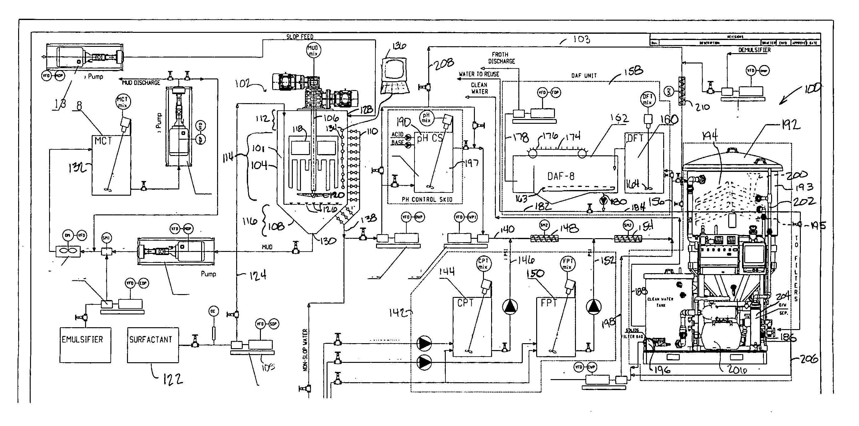
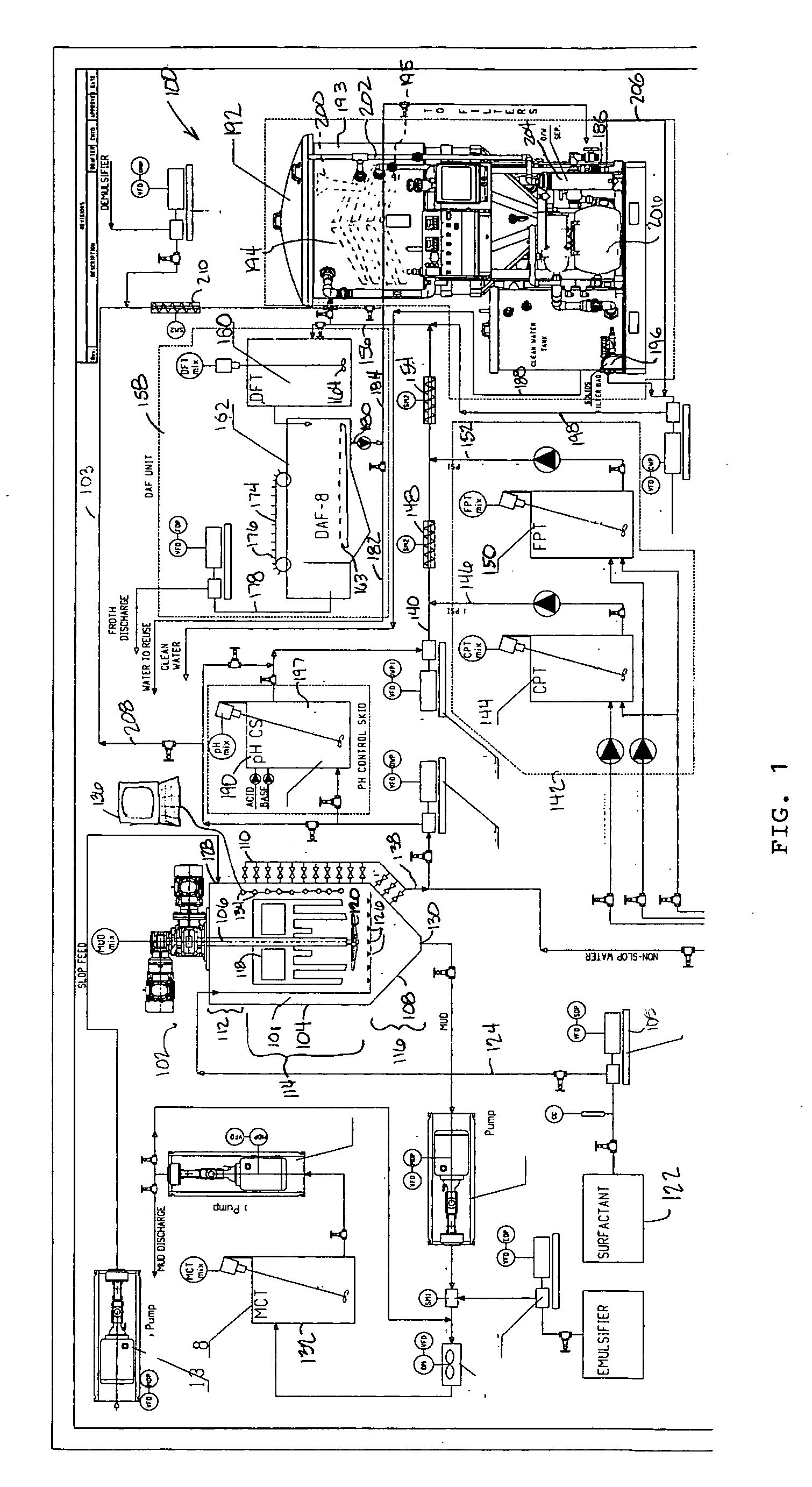
[0015] In one aspect, embodiments disclosed herein are directed to an apparatus 100 and method for removing water from an oil-based drilling fluid. In another aspect, embodiments disclosed herein are directed to a system and method for treating the water for further use or for discharge. In one embodiment, an apparatus 100 includes an separation module 102 and a water treatment module 103.

[0016] Separation Module

[0017] In one embodiment, the separation module 102 separates the slop into mud and water and recovers the non-aqueous drilling fluid. In this embodiment, the separation module includes a separation tank 101. In one embodiment the separation tank 101 is a vertical tank defined by a tank wall 104 having a floor 108 at the lower edge of the tank wall 104. The floor 108 is shaped to urge material towards an outlet 130 through floor 108. In one embodiment of the invention, a water outlet arrangement 110 includes a series of valves along a length of the tank wall 104. In one em...


PUM

PropertyMeasurementUnit
pHaaaaaaaaaa
viscosityaaaaaaaaaa
emulsion stabilityaaaaaaaaaa

Abstract

An apparatus for separating water from oil-based drilling fluid includes an separation tank, a chemical treatment apparatus having one or more de-oiling polymer preparation tanks, and a dissolved air flotation unit. Slop mud is directed into the separation tank where surfactant is added to separate the drilling fluid from oily water. The drilling fluid is drained for further processing. The oily water is removed by an outlet arrangement from the separation tank and directed to an initial treatment line. One or more de-oiling polymers are added to the oily water in the initial treatment line and mixed therewith. The mixture may then be directed to the dissolved air flotation unit where dissolved air is released into the bottom of the mixture. The dissolved air adheres to suspended solids in the mixture and lifts them to the top surface as a froth. The froth is skimmed from the top surface of the mixture and collected. The de-frothed water is reused or directed to a filtration system where it is prepared for discharge. A clarifying tank may be included after the de-oiling polymers are added to further separate the oil and water. The oil is removed from the top surface by a weir while the water is directed to the filtration system and discharged.

Description

[0001] This application claims priority to U.S. Provisional Patent Application Ser. No. 60 / 650,494 filed on Feb. 7, 2005 entitled, “Apparatus for separation of water from oil-based drilling fluid and advanced water treatment” incorporated herein by reference for all purposes.BACKGROUND OF INVENTION [0002] As a result of rigorous environmental regulations shifting towards zero-discharge, drilling wastes are the focus of attention in the oil and gas exploration industry. Drilling with oil-base mud (OBM) or synthetic-base mud (SBM) generates waste streams often referred to as “slop mud” or “slop water.”“Slop water” or “slop mud” are among the significant waste streams from exploration and development activities. Slop water or slop mud is a waste stream which is produced when an oil / synthetic / diesel-based drilling fluid becomes contaminated with water. These waste streams are byproducts of cleaning the drill floor, shaker room, pump room and other areas where spillage and interfaces dur...

Claims


Application Information

Patent Timeline
Patent Type & Authority Applications(United States)
IPC IPC(8): C02F1/24
CPCB01D17/047B01D19/0036B01D21/01B01D21/02B03D1/02B03D1/1431C02F1/001C02F1/24C02F1/283C02F1/52C02F1/56C02F1/66C02F9/00C02F11/14C02F2001/007C02F2101/32C02F2103/10C02F2209/06E21B21/063B01D17/0211B01D17/0214C02F1/288B03D1/247B03D1/1462B03D1/028C02F11/147
Inventor IVAN, CATALIN
Owner MI
Why Eureka
Try Eureka