Piezoelectric vibrator
a technology of piezoelectric and vibrator, which is applied in piezoelectric/electrostrictive/magnetostrictive devices, textiles and papermaking, knitting, etc., can solve the problems of less shock resistance, further decrease in ci value, damage to electronic parts, etc., and achieve great shock resistance
- Summary
- Abstract
- Description
- Claims
- Application Information
AI Technical Summary
Benefits of technology
Problems solved by technology
Method used
Image
Examples
first embodiment
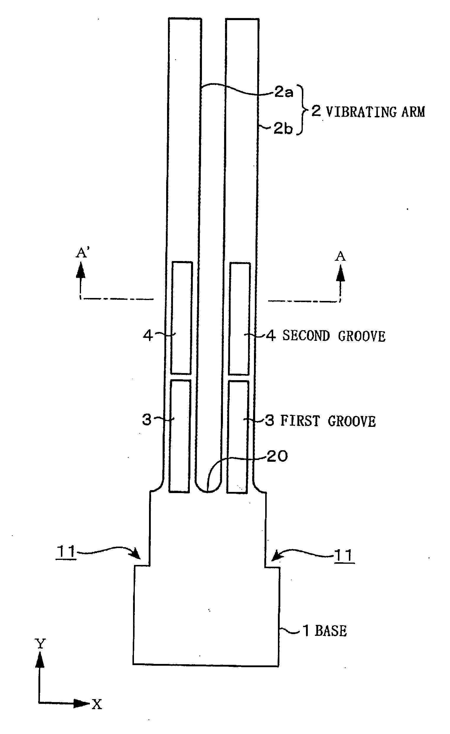
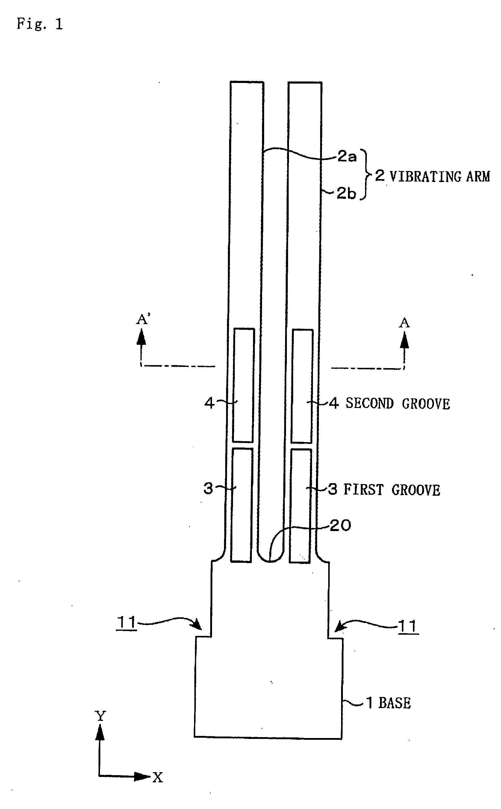
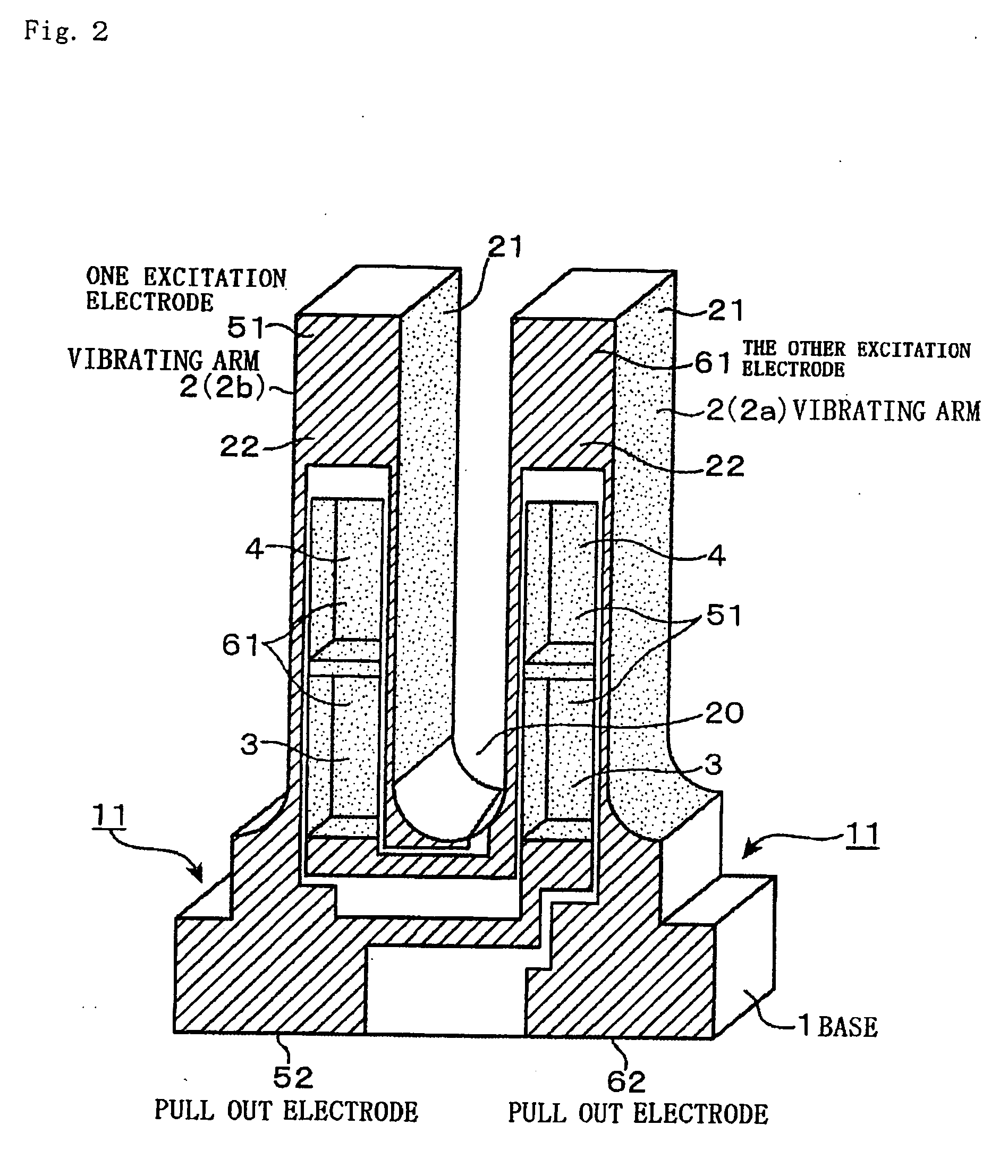
[0024]FIG. 1 is a diagram showing an embodiment of a tuning fork type quartz vibrator relating to the present invention. The quartz vibrator main body (a piece of quartz) in this quartz vibrator includes a substantially square base 1 serving also as a notch portion 11 in which an upper portion of both sides thereof is notched in a rectangle, and two pieces (a pair) of vibrating arms 2 (2a and 2b) extending from the upper side of the base 1 in parallel with a space therebetween, and is formed in an entire shape as a tuning fork type quartz piece. Furthermore, a first groove 3 and a second groove 4 formed by dividing into two parts in the longitudinal direction from the base end of the respective vibrating arms 2 (2a and 2b) toward the tip are provided on the front surface and the back surface of the vibrating arms 2 (2a and 2b).
[0025] A flat surface shape of the base 1 between the pair of vibrating arms 2a and 2b is curved, and a position in the Y-direction of the base end of the fi...
experimental example
Experiment 1
[0033] In a tuning fork type quartz vibrator described in a previously described embodiment, a ratio L2 / L1 of the length L2 of the first groove 3 to the length L1 from the base of the first groove 3 to the tip of the second groove 4 was changed variously, and the strength of respective quartz vibrators was checked. The L2 / L1 is set in the following 5 ways: 0%, 12.5%, 35%, 50% and 65%, expressed by a percentage % ((L2 / L1)×100). 0% means forming one continuous groove without dividing it.
[0034] Other conditions are as follows. The length L0 of the vibrating arms 2 (2a and 2b) is 1650 μm, the L1 from the base of the first groove 3 to the tip of the second groove 4 is 847 μm, the space d of the first groove 3 and the second groove 4 is 10 μm, the length L3 from the bottom surface of the base 1 to the lowest portion 20 of the fork portion of the tuning fork is 600 μm, the width W1 of the vibrating arms 2 (2a and 2b) is 100 μm, the width W2 of the groove 3 is 65 μm, and the w...
experiment 2
[0037] Next, an experiment to find an appropriate value of a space d between the first groove 3 and the second groove 4 was carried out. In this experiment, L2 / L1 was set to be 35% (0.35), and the space d between the first groove 3 and the second groove 4 was changed variously by changing the position on the base end side of the second groove 4 to set d / L1 in 5 ways: 0%, 0.6%, 1.0%, 1.2%, and 2.5%. Other conditions are the same as in Experiment 1. Strength of each quartz vibrator was examined in the same way as in Example 1. The result is as shown in Table 2 and FIG. 7. Note that the time of d / L1 being 1.2% corresponds to the time of d in the previous Experiment 1 being 10 μm.
TABLE 2L2 / L1First TimeSecond TimeThird TimeAverage(%)(g)(g)(g)(g)07.38.86.07.40.68.59.26.98.21.07.810.38.99.01.210.99.68.09.52.524192021
[0038] From this result, it can be said that the wider the space d between both grooves 3 and 4, in other words, the greater the d / L1, the greater the strength of the quartz ...
PUM
 Abstract
Description
Claims
Application Information
 - R&D
- Intellectual Property
- Life Sciences
- Materials
- Tech Scout
- Unparalleled Data Quality
- Higher Quality Content
- 60% Fewer Hallucinations
Browse by: Latest US Patents, China's latest patents, Technical Efficacy Thesaurus, Application Domain, Technology Topic, Popular Technical Reports.
© 2025 PatSnap. All rights reserved.Legal|Privacy policy|Modern Slavery Act Transparency Statement|Sitemap|About US| Contact US: help@patsnap.com


