Device for counting micro particles

a micro-particle and counting technology, applied in the field of micro-particle counting devices, can solve the problems of inconvenient operation, too expensive analysis devices developed for blood analysis, chemometec, denmark, etc., and achieve the effect of improving the accuracy of counting

Active Publication Date: 2006-08-24
NANOENTEK
View PDF13 Cites 45 Cited by
  • Summary
  • Abstract
  • Description
  • Claims
  • Application Information

AI Technical Summary

Benefits of technology

[0011] Particularly, the chip shifter shifts the position of the chip by a predetermined distance at every predetermined time interval in order that a certain area adjacent to the area photographed just before by a CCD camera is shifted to the point where the light is incident. Therefore, sub-areas on the chip are photographed successively. The counting part counts the number of micro particles in each sub-area, and adds them together to calculate the total number of micro particles in the samples. Therefore it is possible to count micro particles in the sample promptly and accurately. The structure of the device is simple, and it can be used in convenience, and the price is low, too.
[0024] Thus, the micro-particle counting device according to the present invention can enhance the precision of counting since it photographs the sample chip by each sub-area and counts the particles. Further, although the micro-particles are maldistributed, there are no errors since it counts all the area of the sample.

Problems solved by technology

The analysis devices developed for blood analysis, for example, Neucleocounterâ„¢ of Chemometec, Denmark, are too expensive, and the operating method is so difficult that it is not easy to use the device for not only the ordinary person, but also the analysis expert.
Also, as the sample chip for the analysis device is fabricated separately and is too expensive, it is a burden to use such device.
Since medical technologists count them by hand, the errors in the inspection occur frequently, and it takes much time to inspect.
Further, in case of using the previously-developed device or counting the cells by hand, there is a problem that a person is likely to expose to a harmful dying reagent in the process of experiment.

Method used


Image

  • Device for counting micro particles
  • Device for counting micro particles
  • Device for counting micro particles

Examples


first embodiment

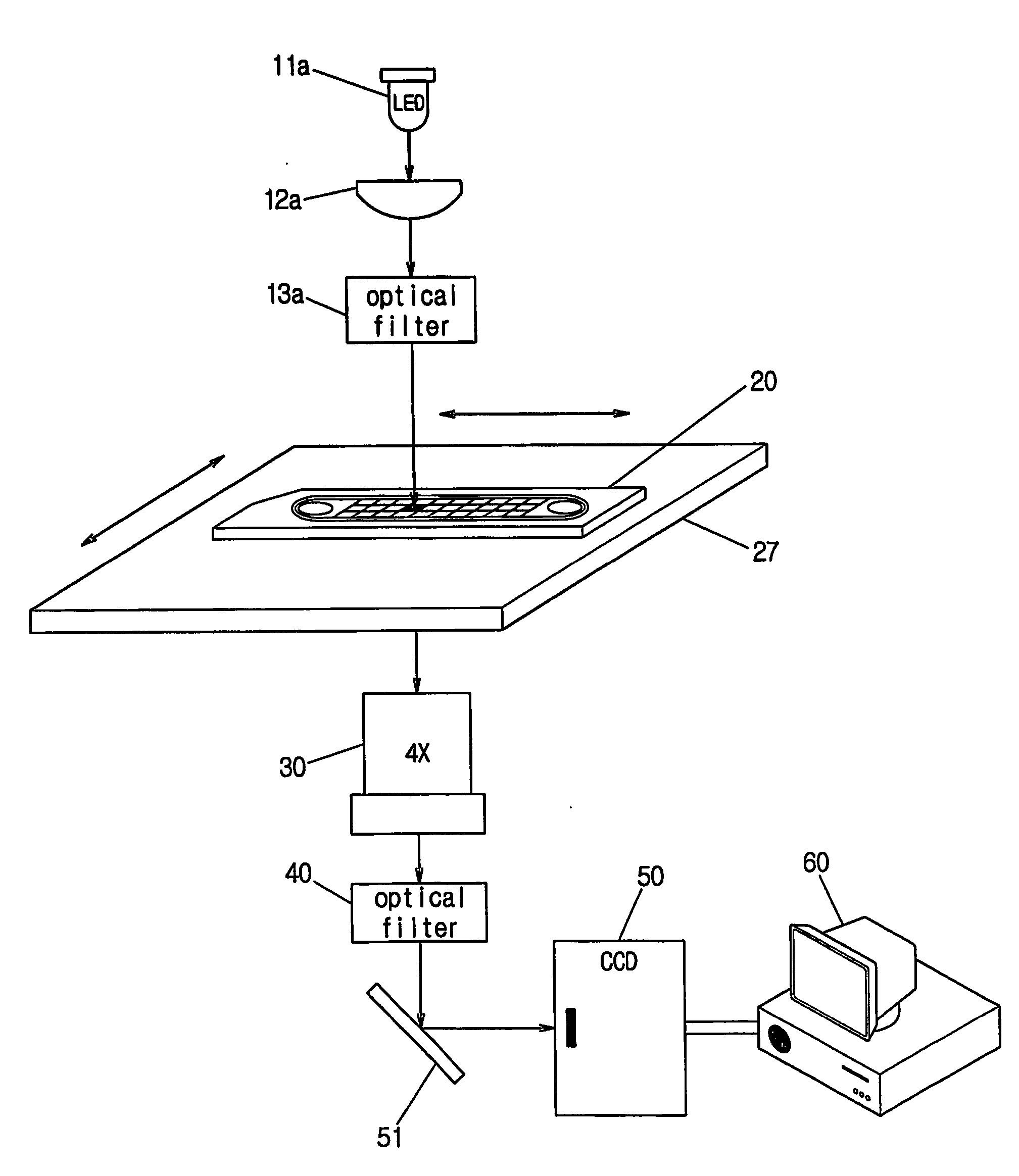
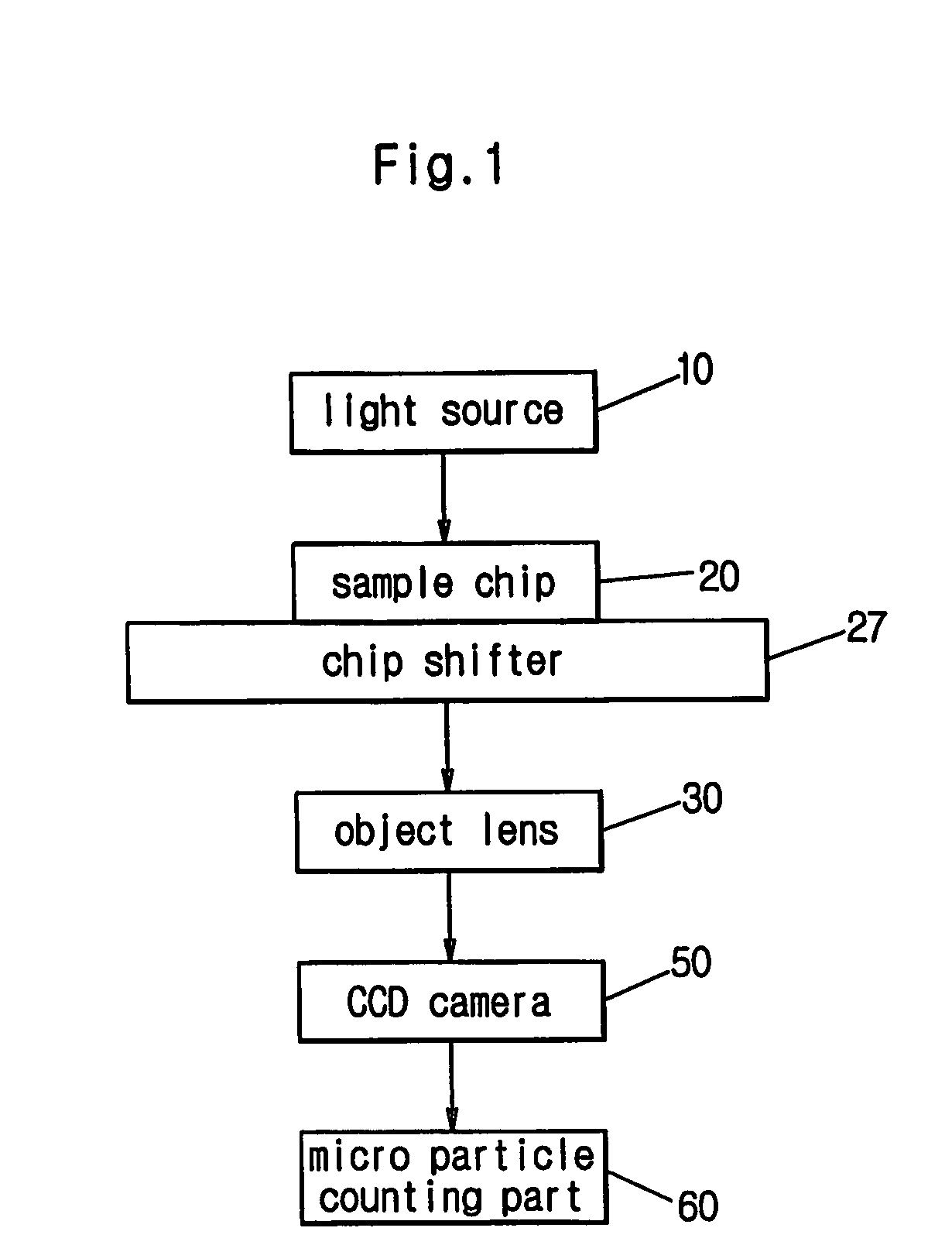
[0077]FIG. 4 depicts the first embodiment, which comprises the light source of LED. The device depicted in FIG. 4 is to count erythrocytes, which comprises:

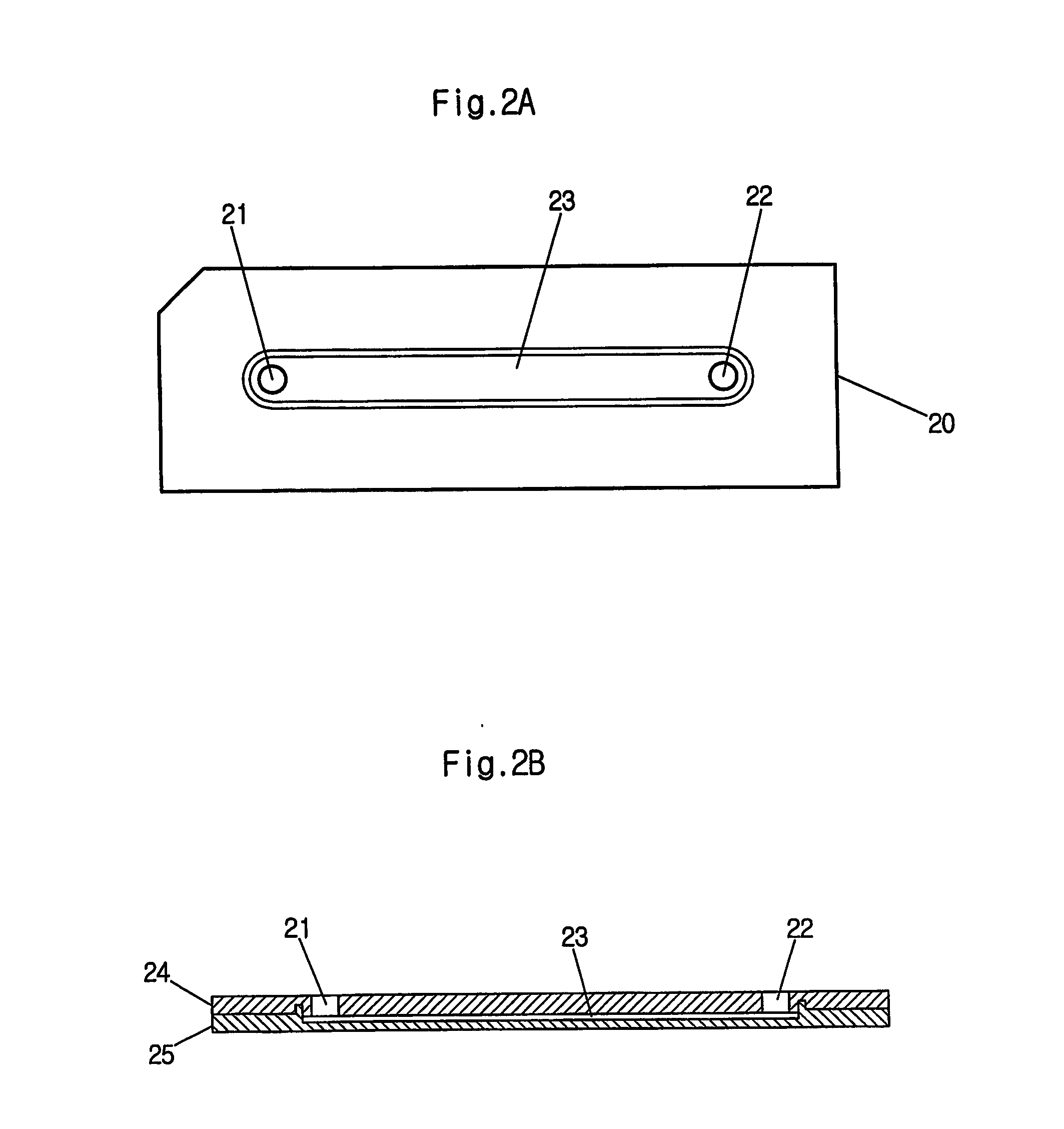
[0078] a sample chip(20) wherein a sample containing the erythrocytes is located at the reading part with predetermined volume;

[0079] an LED(11a) projecting ultraviolet or visible light into a sub-area on the ample chip;

[0080] an incident light control lens(12a) controlling the amount of light emitted from the LED(11a) and the distance of focus,

[0081] an incident optical filter(13a) which passes the light with a specified wave length passing the incident light control lens(12a), emits the light onto the sample chip;

[0082] an object lens(30) facing to the chip to magnify the image of the sample;

[0083] an optical filter(40) which passes the light with a specified wave length passing the object lens(30);

[0084] a CCD camera(50) photographing the image of the sample which passes the optical filter(40);

[0085] a micro particle co...

second embodiment

[0088]FIG. 5 depicts the second embodiment, which comprises the light source of LASER(11b). The device depicted in FIG. 5 is to count cells containing a cell nucleus such as a leukocyte or somatic cell, which comprises:

[0089] a sample chip(20) wherein a sample containing cells and dyeing reagent at the reading part with predetermined volume;

[0090] a LASER source(11b) projecting light into a sub-area on the sample chip;

[0091] an incident light control lens(12b) controlling the amount of light emitted from the LASER source(11b) and the distance of focus, and emitting the light onto the sample chip;

[0092] an object lens(30) facing to the chip to magnify the image of the sample;

[0093] an optical filter(40) which passes the light with a specified wave length passing the object lens(30);

[0094] a CCD camera(50) photographing the image of the sample, which passes the optical filter(40);

[0095] a micro particle counting part(60) counting the cells on the sub-area photographed by the ima...


PUM

PropertyMeasurementUnit
heightaaaaaaaaaa
volumeaaaaaaaaaa
sizeaaaaaaaaaa

Abstract

A device for counting micro particles is presented. The device comprises a light source; a chip containing micro particles; an object lens; a CCD camera; a counting part; and a shifter for shifting the position of the chip. It is easy to count the number of micro particles, such as red blood cells or somatic cells, by using the device. The shifter shifts the position of the chip by a predetermined distance at every predetermined time interval in order that a certain area adjacent to the area photographed just before is shifted to the point where the light is incident. Therefore, sub-areas on the chip are photographed successively. The counting part counts the number of micro particles in each sub-area, and adds them together to calculate the total number of micro particles in the samples.

Description

TECHNICAL FIELD [0001] The present invention relates to a device for counting the number of micro particles such as cells. More specifically, the present invention relates to a device for counting micro particles, which comprises the sample chip wherein a sample containing the particles is located at a reading part; a light source projecting light into a sub-area at the sample chip; an object lens to magnify the image of the sample that is formed at the sub-area; an image photographing part photographing the image of the sample; a micro particle counting part counting micro particles in the sub-area using the photographed image; and the chip shifting part shifting the sample chip. BACKGROUND ART [0002] For the patients suffer from AIDS, leukemia, or anemia, it is necessary to count the number of particles of leukocyte or erythrocyte related to such disease in the blood of the patients in order to diagnose the diseases, to monitor the progress of the diseases, and to verify the effec...

Claims


Application Information

Patent Timeline
Patent Type & Authority Applications(United States)
IPC IPC(8): G01N33/48B01L3/00G01N15/14G01N21/64
CPCB01L3/5027G01N15/147G01N15/1475G01N21/6428G01N21/6458G01N2015/1486
Inventor CHANG, JUN KEUNCHUNG, CHANILHUR, DAE SUNGDAN CHIN-YU, ALEXEYCHUNG, SEOKHWANG, JEONG KUJEON, SEUNG HWA
Owner NANOENTEK
Why Eureka
Try Eureka