
Method and apparatus for EUV light source target material handling

a technology of target material and euv light source, which is applied in the field of laser-produced plasma to achieve the effect of stable long-term performance and avoidance of clogging

Active Publication Date: 2006-08-31
ASML NETHERLANDS BV
View PDF99 Cites 74 Cited by
  • Summary
  • Abstract
  • Description
  • Claims
  • Application Information

AI Technical Summary

Benefits of technology

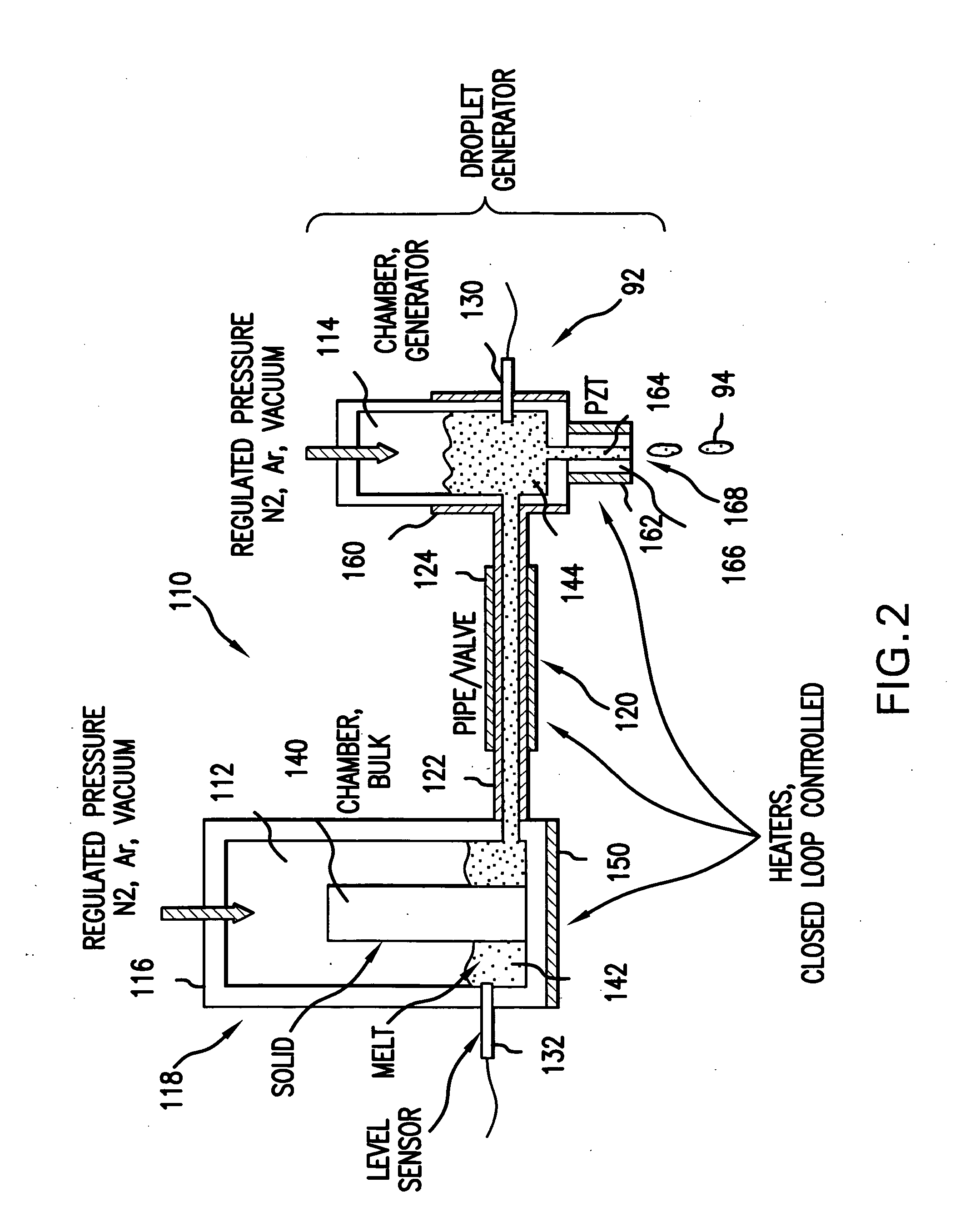
[0007] The method and apparatus may comprise providing EUV light source plasma source material in a plasma source material handling system comprising a droplet generator having a droplet generator plasma source material reservoir; a droplet formation capillary maintained within a selected range of temperatures sufficient to keep the plasma source material in a liquid form and a plasma source material supply system having a supply reservoir and a transfer mechanism transferring liquid plasma source material from the supply reservoir to the droplet generator plasma source material reservoir, comprising the steps of: utilizing an initial cleaning and conditioning process to achieve stable long-term performance, due to initial contamination due to liquid metal and plasma source material handling system component chemical interaction by providing an initial flush of the system. The flush is carried out at a selected temperature and introduced in sufficient quantity to avoid clogging. The method and apparatus may comprise subjecting plasma source material handling system component surfaces in contact with the plasma source material to a passivation process. The passivation material may comprise an acid bath to leech out materials through the component surfaces reactive with molten plasma source material. The method and apparatus may comprise choosing materials for surfaces wetted by the liquid plasma source material to substantially limit the formation of intermetallic compounds by the wetted surface material and the liquid plasma source material. The method and apparatus may comprise providing EUV light source plasma source material in a plasma source material handling system comprising a droplet generator having a droplet generator plasma source material reservoir; a droplet formation capillary maintained within a selected range of temperatures sufficient to keep the plasma source material in a liquid form and a plasma source material supply system having a supply reservoir and a transfer mechanism transferring liquid plasma source material from the supply reservoir to the droplet generator plasma source material reservoir, which may comprise the steps of: utilizing an inline filter intermediate the plasma source material supply system and the droplet generator plasma source material reservoir to prevent contaminants in the plasma source material reservoir from reaching the droplet generator plasma source material reservoir. The method and apparatus may comprise providing EUV light source plasma source material in a plasma source material handling system comprising a droplet generator having a droplet generator plasma source material reservoir; a droplet formation capillary maintained within a selected range of temperatures sufficient to keep the plasma source material in a liquid form and a plasma source material supply system having a supply reservoir and a transfer mechanism transferring liquid plasma source material from the supply reservoir to the droplet generator plasma source material reservoir, which may comprise the steps of: maintaining temperatures in at least one selected portion of the material handling system so as to avoid thermal gradients within the at least one selected portion sufficient to cause solubility differences sufficient to precipitate out insoluble compounds as particulate. The method and apparatus may comprise maintaining at least one selected portion of the material handling system downstream of a valve in the transfer mechanism at an elevated temperature sufficient to avoid blockage of at lest one narrowed passage portion of the at least one selected portion. The at least one selected portion is selected from the capillary, a nozzle at the discharge end of the capillary and an output orifice in the nozzle. The method and apparatus may comprise an EUV light source plasma source material handling system which may comprise: a droplet generator having a droplet generator plasma source material reservoir in fluid communication with a droplet formation capillary and maintained within a selected range of temperatures sufficient to keep the plasma source material in a liquid form; a plasma source material supply system having a supply reservoir in fluid communication with the droplet generator plasma source material reservoir and holding at least a replenishing amount of plasma source material in liquid form for transfer to the droplet generator plasma source material reservoir, while the droplet generator at temperature; a storage mechanism storing plasma source material in a solid form within the droplet generator plasma source material supply system to replenish the plasma source material in the molten portion of the supply system reservoir. the method and apparatus may comprise a porous separator separating a solid form storage portion of the plasma source material supply system reservoir from the molten plasma source material supply system reservoir; a heating mechanism heating the porous separator to inject liquid plasma source material into the molten portion of the plasma source material supply system reservoir by melting at least a portion of the solid form of the plasma source material. The method and apparatus may comprise a hopper in the plasma source material supply system reservoir containing plasma source material in a solid dispensable form comprising a remotely operated dispensing mechanism delivering a selected quantity of the solid dispensable plasma source material to the molten plasma material portion of the plasma source material supply system reservoir. The dispensable form may comprise a pellet form or a powder form. The apparatus and method may comprise a holding mechanism holding the solid form plasma source material separate from the molten portion of the plasma source material supply system reservoir; a segmented heating mechanism selectively heating a selected segment of the solid form plasma source material in the plasma source material supply system reservoir to replenish the liquid form plasma source material in the molten portion of the plasma source material supply system reservoir.

Problems solved by technology

A number of problems are known to exist in the art regarding the handling of the target material, e.g., liquid metal feeding to a mechanism for the formation of target droplets either of the metal itself or a suspension, dispersion or other mixture of the target material with a liquid that is not reactive with the target material, e.g., water or alcohol for a tin metal plasma source material and a liquid plasma source material compound such as Li(CH3).

Method used


Image

  • Method and apparatus for EUV light source target material handling
  • Method and apparatus for EUV light source target material handling
  • Method and apparatus for EUV light source target material handling

Examples


Embodiment Construction

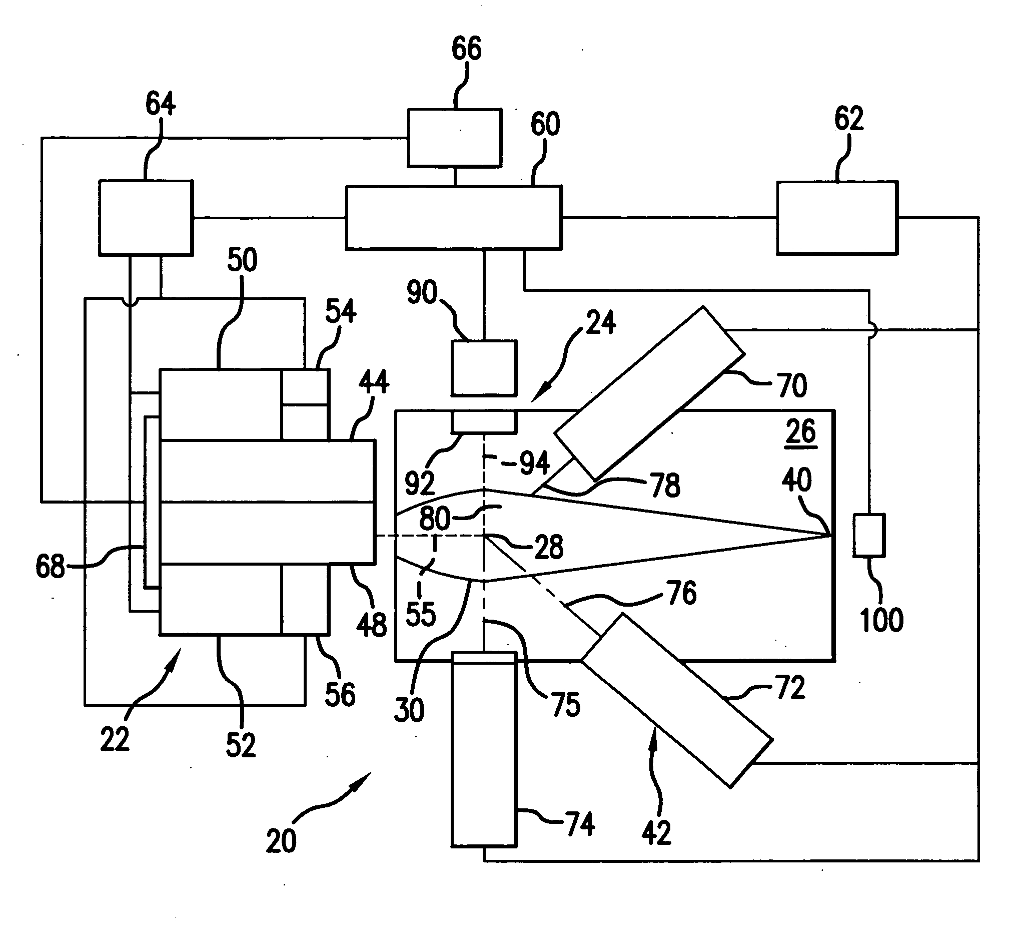
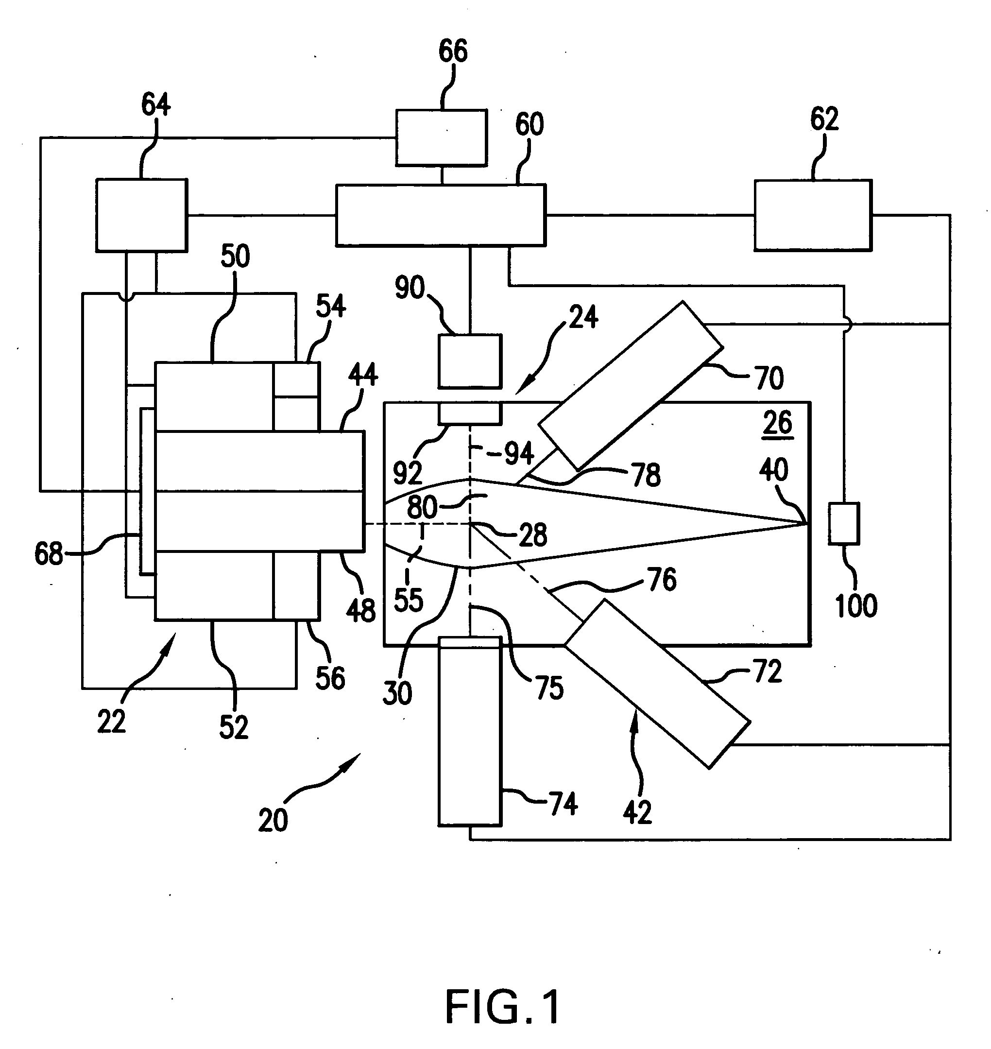
[0016] Turning now to FIG. 1 there is shown a schematic view of an overall broad conception for an EUV light source, e.g., a laser produced plasma EUV light source 20 according to an aspect of the present invention. The light source 20 may contain a pulsed laser system 22, e.g., one or more gas discharge excimer or molecular fluorine lasers operating at high power and high pulse repetition rate and may be one or more MOPA configured laser systems, e.g., as shown in U.S. Pat. Nos. 6,625,191, 6,549,551, and 6,567,450. The light source 20 may also include a target delivery system 24, e.g., delivering targets in the form of liquid droplets, solid particles or solid particles contained within liquid droplets. The targets may be delivered by the target delivery system 24, e.g., into the interior of a chamber 26 to an irradiation site 28, otherwise known as an plasma formation site or the sight of the fire ball, i.e., where irradiation by the laser causes the plasma to form from the target...


PUM


Abstract

An EUV light source plasma source material handling system and method is disclosed which may comprise a droplet generator having a droplet generator plasma source material reservoir in fluid communication with a droplet formation capillary and maintained within a selected range of temperatures sufficient to keep the plasma source material in a liquid form; a plasma source material supply system having a supply reservoir in fluid communication with the droplet generator plasma source material reservoir and holding at least a replenishing amount of plasma source material in liquid form for transfer to the droplet generator plasma source material reservoir, while the droplet generator is on line; a transfer mechanism transferring liquid plasma source material from the supply reservoir to the droplet generator plasma source material reservoir, while the droplet generator is on line. The supply reservoir may comprise a solid form of the plasma source material used to periodically form from a portion of the material in solid form the material in liquid form.

Description

RELATED APPLICATIONS [0001] The present application is a continuation in part of United states patent application Ser. No. 11 / 067,124, entitled METHOD AND APPARATUS FOR EUV PLASMA SOURCE TARGET DELIVERY, filed Feb. 25, 2005, Attorney Docket No. 2004-0008-01, the disclosures of each of which is also hereby incorporated by reference. [0002] The present application is related to co-pending U.S. application Ser. No. 11 / 021,261, entitled EUV LIGHT SOURCE OPTICAL ELEMENTS, filed on Dec. 22, 2004, Attorney Docket No. 2004-0023-01, and Ser. No. 10 / 979,945, entitled EUV COLLECTOR DEBRIS MANAGEMENT, filed on Nov. 1, 2004, Attorney Docket No. 2004-0088-01, Ser. No. 10 / 979,919, filed on Nov. 1, 2004, entitled LPP EUV LIGHT SOURCE, Attorney Docket No. 2004-0064-01, Ser. No. 10 / 900,839, entitled EUV LIGHT SOURCE, Attorney Docket No. 2004-0044-01, Ser. No. 10 / 798,740, entitled COLLECTOR FOR EUV LIGHT SOURCE, Attorney Docket No. 2003-0083-01, the disclosures of which are hereby incorporated by refe...

Claims


Application Information

Patent Timeline
Patent Type & Authority Applications(United States)
IPC IPC(8): H05G2/00
CPCH05G2/003H05G2/005H05G2/006H05G2/00
Inventor ALGOTS, J. MARTINHEMBERG, OSCARCHUNG, TAE H.
Owner ASML NETHERLANDS BV
Learn More