Organic electroluminescence type display apparatus

a display apparatus and electroluminescence technology, applied in the field of electroluminescence display apparatuses, can solve the problems of affecting the luminous efficiency of the resistance of the device is abnormally increased, and the above-mentioned reflected light is caused by a big loss, etc., to achieve enhanced hole injection efficiency to the organic el layer, high reflectivity efficiency, and high luminous efficiency

Inactive Publication Date: 2006-08-31
MITSUBISHI ELECTRIC CORP
View PDF10 Cites 27 Cited by
  • Summary
  • Abstract
  • Description
  • Claims
  • Application Information

AI Technical Summary

Benefits of technology

[0016] The anode is composed of a two-layer film including Al alloy film containing impurities of at least one of the transition metals of the eighth group of 3d selected from Fe, Co and Ni and also including a light transmitting conductive oxide film laminated on the Al alloy film. Accordingly, it is possible to prevent a generation of the electrically insulating interface reacting layer on the interface between Al alloy film and the light transmitting conductive oxide film. Accordingly, the reflecting efficiency of light generated from the organic EL element is high, and the hole injection efficiency to the organic EL layer can be enhanced. Therefore, it is possible to provide an organic electroluminescence type display apparatus, the luminous efficiency of which is high, capable of displaying a bright image.

Problems solved by technology

However, in the case of the bottom emission type, the following problems may be encountered.
Therefore, when Cr or Mo is applied to the anode, a big loss is caused in the above reflected light.
Therefore, the resistance of the device is abnormally increased, which is a well known problem.
Accordingly, the hole injection efficiency to the organic EL layer is remarkably deteriorated.
In order to solve this problem, in the case where such a method is employed that another metallic film is added between the conductive oxide film and Al alloy film, since it is difficult for this metal to be optimized from the viewpoint of the light reflectance, it is impossible to obtain a high light reflectance necessary for the anode.
Therefore, it is difficult for this method to be put into practical use.
Further, in the case of Al film, surface irregularities such as hillocks tend to occur, and further a short mode failure with the opposed cathode through the organic EL layer tends to occur.
Furthermore, surface defect referred to as dark spots tend to occur.
Therefore, the above methods can not be substantially applied to an actual device.

Method used


Image

  • Organic electroluminescence type display apparatus
  • Organic electroluminescence type display apparatus
  • Organic electroluminescence type display apparatus

Examples


embodiment 1

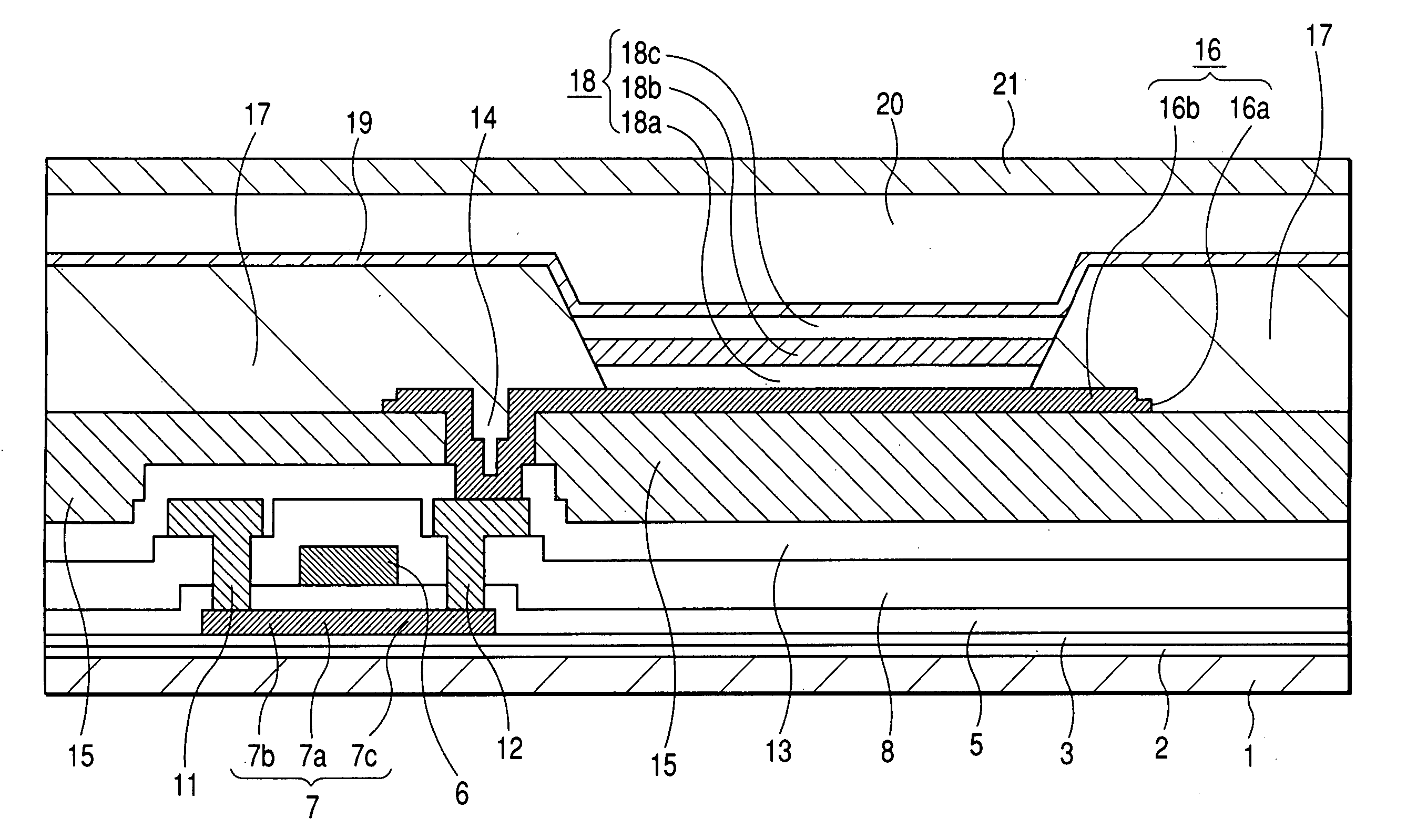
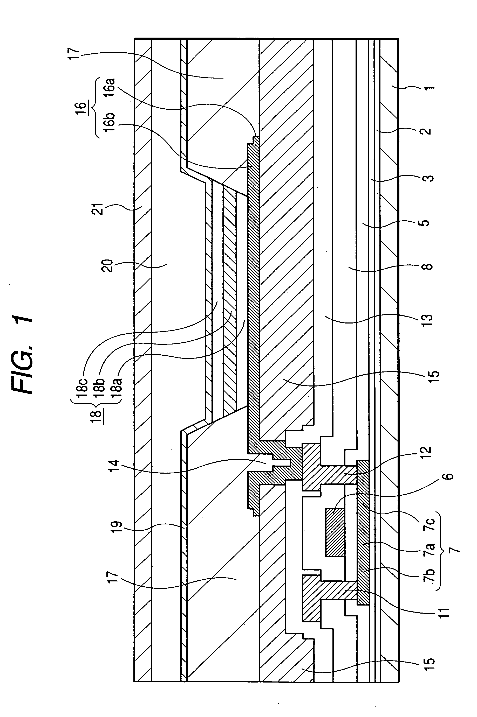
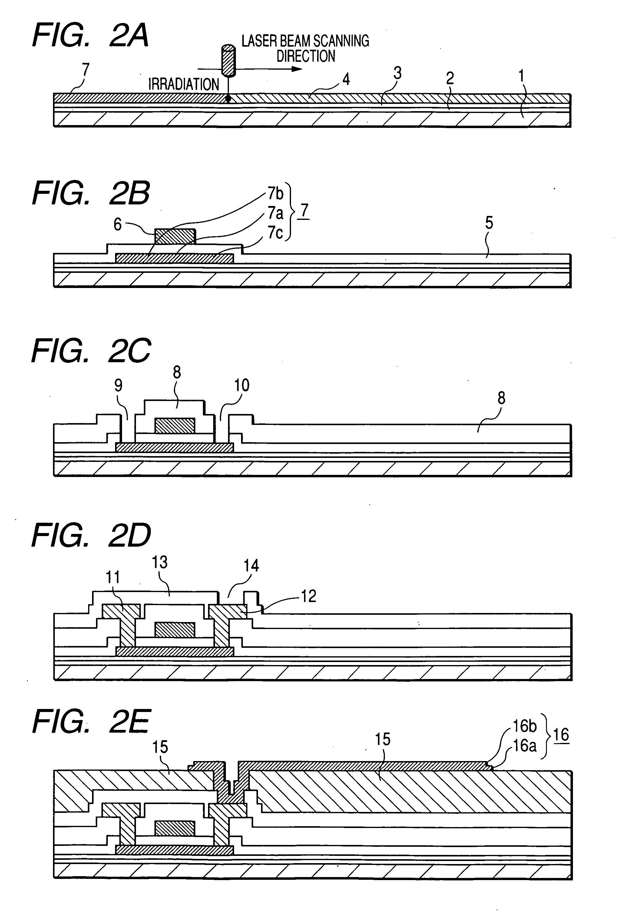
[0024]FIG. 1 is a sectional view of a picture element portion showing TFT substrate, which composes an organic electroluminescence type display apparatus of Embodiment 1 of the present invention, and also showing an organic EL element formed in an upper portion of TFT substrate. In FIG. 1, SiN film 2 is a transmitting insulating film formed on the insulating substrate 1, and the polysilicon film 7 having a channel region 7a, a source region 7b and a drain region 7c is provided on SiO2 film 3. The gate insulating film 5 is formed in such a manner that it covers SiO2 film 3 and the polysilicon film 7. On the gate insulating film 5, the gate electrode 6 and the first inter layer insulating film 8 made of SiO2 are formed. The source electrode 11 and the drain electrode 12 are provided on the first inter layer insulating layer 8 and respectively connected to the source region 7b and the drain region 7c via the contact holes 9, 10. The thin film transistor is composed as described above. ...


PUM

PropertyMeasurementUnit
thicknessaaaaaaaaaa
thicknessaaaaaaaaaa
thicknessaaaaaaaaaa

Abstract

An organic electroluminescence type display apparatus of top emission type, in which a thin film transistor (TFT), a flattening film made of organic resin and an organic EL element, in which at least an anode, an electroluminescence layer and a cathode are laminated on the flattening film in this order, are formed in each picture element in a display region on a substrate. The anode is composed of at least two layer film including an aluminum (Al) alloy film containing as a impurity at least one of transition metals of the eighth group of 3d into Al and including a light transmitting conductive oxide film laminated on the Al alloy film.

Description

BACKGROUND OF THE INVENTION [0001] 1. Field of the Invention [0002] The present invention relates to an electro-optic display apparatus. More particularly, the present invention relates to an organic electroluminescence type display apparatus in which an organic electroluminescence type element, which will be referred to as an organic EL element hereinafter, is formed in a picture element region as an electro-optic element on an active matrix type substrate on which TFT is formed. [0003] 2. Description of the Related Art [0004] In recent years, an organic electroluminescence type display apparatus, in which a light emitter such as an organic EL element is used as an electro-optic element, has been commonly used as one of the display panels. [0005] The organic EL element is essentially composed in such a method that an electroluminescence layer containing an organic EL layer is interposed between the anode and the cathode. When voltage is impressed between the anode and the cathode, ...

Claims


Application Information

Patent Timeline
Patent Type & Authority Applications(United States)
IPC IPC(8): H05B33/26H01L51/50
CPCH01L27/3244H01L51/5218H01L51/5271H01L2251/5315H10K59/12H10K50/818H10K50/856H10K2102/3026G08G1/0962H04M1/6075G01S19/13G08G1/0969H04M2250/52H04M2201/50H04M1/724
Inventor NAGAYAMA, KENSUKEISHIGA, NOBUAKIINOUE, KAZUNORITAKEGUCHI, TORUFUCHIGAMI, HIROYUKI
Owner MITSUBISHI ELECTRIC CORP
Why Eureka
Try Eureka