Using detected visual cues to change computer system operating states

a technology of visual cues and computer system, applied in the field of computer systems, to achieve the effect of improving the overall computing experience of users, reducing power consumption, and better managing power consumption

Inactive Publication Date: 2006-08-31
MICROSOFT TECH LICENSING LLC
View PDF14 Cites 198 Cited by
  • Summary
  • Abstract
  • Description
  • Claims
  • Application Information

AI Technical Summary

Benefits of technology

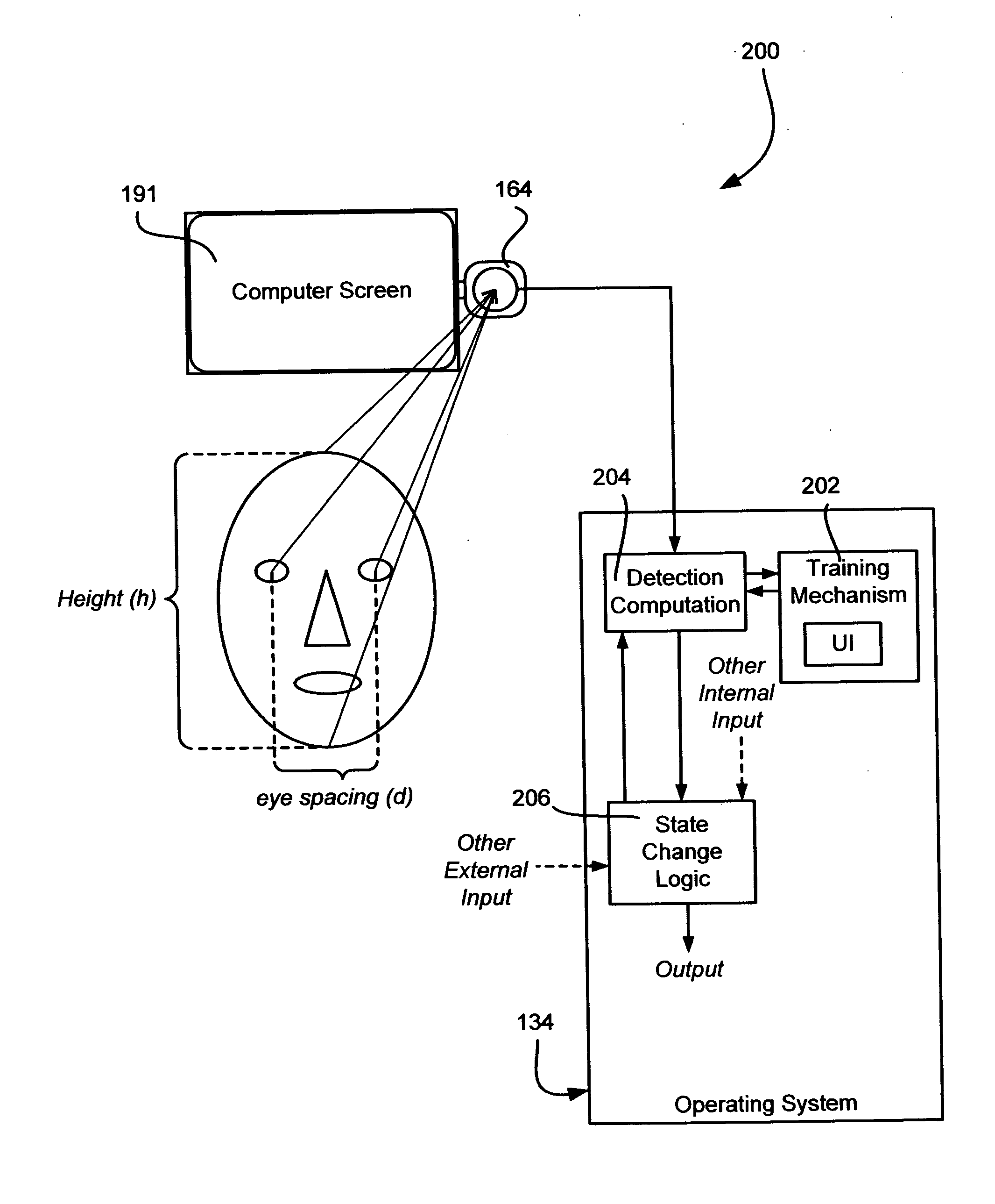
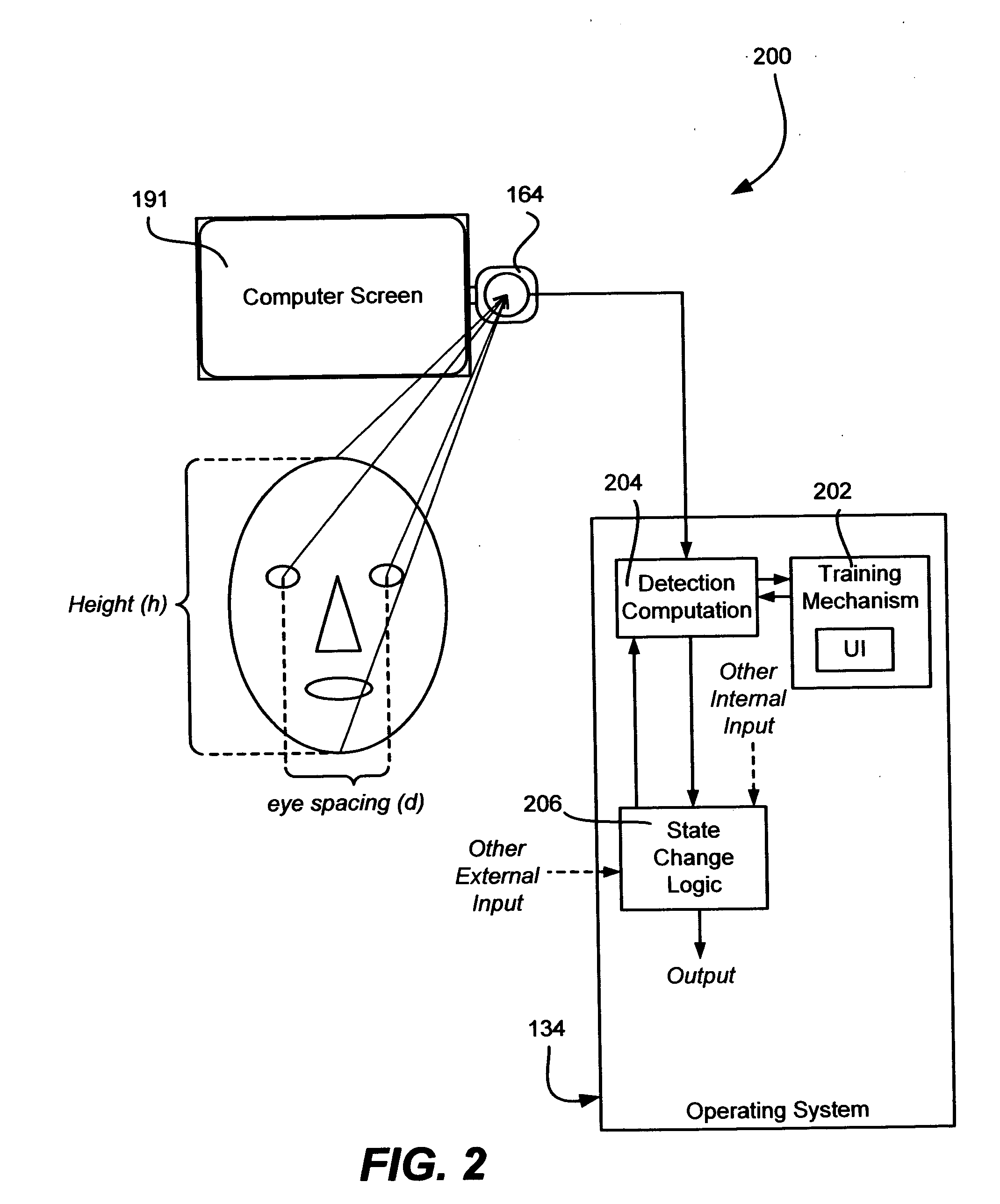
[0006] Briefly, the present invention provides a system and method that uses one or more computer cameras, along with visual cues based on presence detection, pose detection and / or gaze detection software, to improve a user's overall computing experience with respect to performing a number of non-camera related computing tasks. To this end, by detecting via visual cues as to whether and / or where a user is looking at a point such as a display monitor, one or more computer operating states may be changed to accomplish non-camera related computing tasks. Examples include better management of power consumption by reducing power when the user is not looking at the display, turning voice recognition on and off based on where the user is looking, faster-perceived startup by resuming from lower-power states based on user presence, different application program behavior, and other improvements. Visual cues may be used alone or in conjunction with other criteria, such as the current operating context and possibly other sensed data. For example, the time of day may be a factor in sensing motion, possibly including turning the camera on (which may be turned off after some time with no motion sensed) to again look for motion, such as to wake a computer system into a higher-powered state in anticipation of usage as soon as motion is sensed at the start of a workday.

Problems solved by technology

Similarly, one of the most significant challenges to speech recognition is determining, without manual input or specific verbal cues, when the user is intending to speak to the computer system / device, as opposed to otherwise just talking.

Method used


Image

  • Using detected visual cues to change computer system operating states
  • Using detected visual cues to change computer system operating states
  • Using detected visual cues to change computer system operating states

Examples


Embodiment Construction

Exemplary Operating Environment

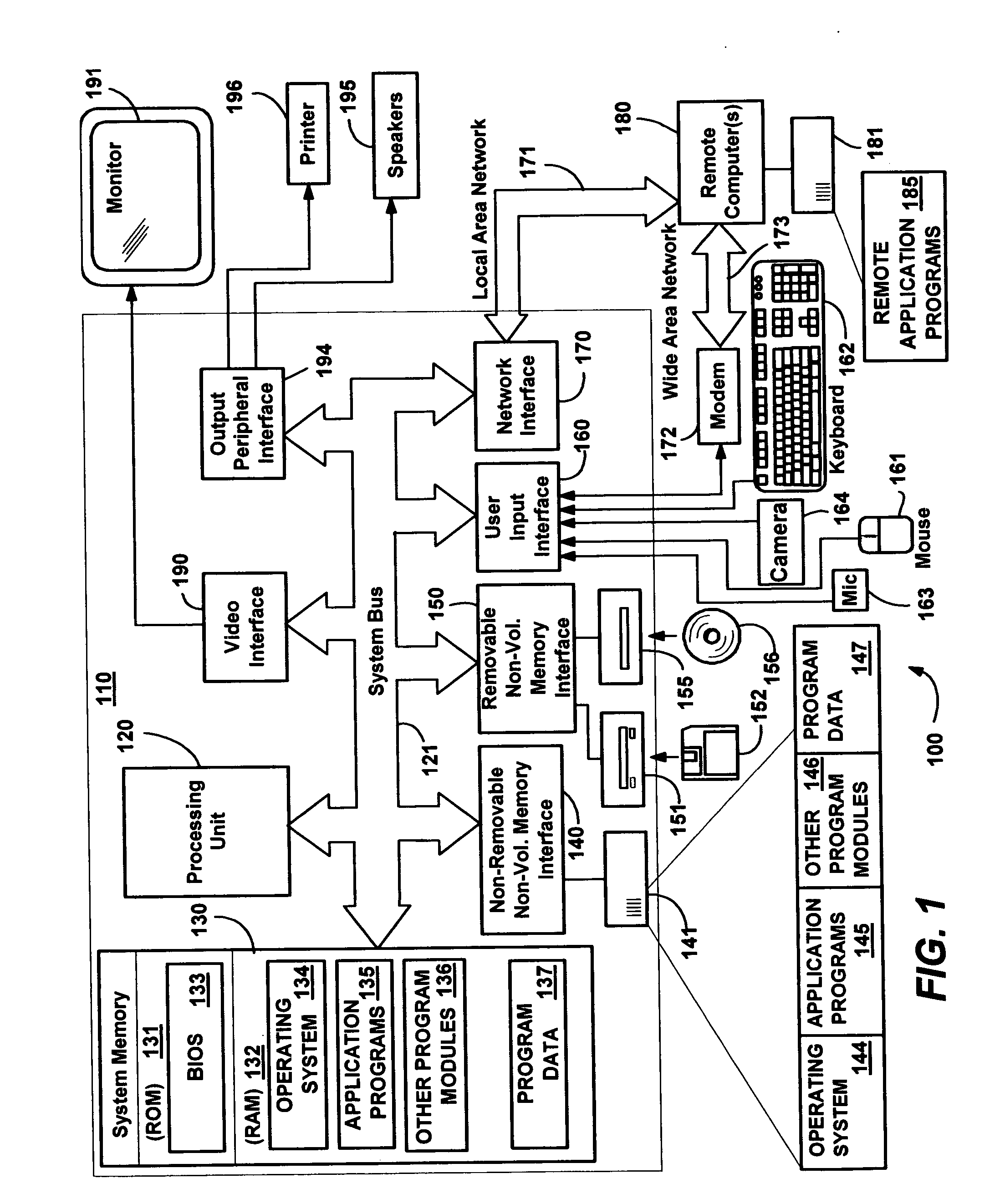
[0018]FIG. 1 illustrates an example of a suitable computing system environment 100 on which the invention may be implemented. The computing system environment 100 is only one example of a suitable computing environment and is not intended to suggest any limitation as to the scope of use or functionality of the invention. Neither should the computing environment 100 be interpreted as having any dependency or requirement relating to any one or combination of components illustrated in the exemplary operating environment 100.

[0019] The invention is operational with numerous other general purpose or special purpose computing system environments or configurations. Examples of well known computing systems, environments, and / or configurations that may be suitable for use with the invention include, but are not limited to: personal computers, server computers, hand-held or laptop devices, tablet devices, multiprocessor systems, microprocessor-based systems, ...


PUM


Abstract

Described is a method and system that uses visual cues from a computer camera (e.g., webcam) based on presence detection, pose detection and/or gaze detection, to improve a user's computing experience. For example, by determining whether a user is looking at the display or not, better power management is achieved, such as by reducing power consumed by the display when the user is not looking. Voice recognition such as for command and control may be turned on and off based on where the use is looking when speaking. Visual cues may be used alone or in conjunction with other criteria, such as mouse or keyboard input, the current operating context and possibly other data, to make an operating state decision. Interaction detection is improved by determining when the user is interacting by viewing the display, even when not physically interacting via an input device.

Description

FIELD OF THE INVENTION [0001] The invention relates generally to computer systems, and more particularly to controlling computer systems that have connected cameras. BACKGROUND OF THE INVENTION [0002] The use of cameras with a personal computer system (computer cameras) is becoming commonplace. Such computer cameras, often referred to as “webcams” because many users use computer cameras for sending live video over the web, may be built into a personal computer, or may be added later, such as via a USB (universal serial bus) connection. Add-on computer cameras may be positioned on small stands, but are typically clipped to the user's monitor. [0003] Computer cameras may be used in conjunction with software for face-tracking, in which the camera can adjust itself to essentially follow around a user's face. For example, face detection is described in U.S. patent application Ser. No. 10 / 621,260 filed Jul. 16, 2003, entitled “Robust Multi-View Face Detection Methods and Apparatuses.” Mor...

Claims


Application Information

Patent Timeline
Patent Type & Authority Applications(United States)
IPC IPC(8): G09G5/00
CPCA61F4/00G06F1/3203G06F1/3231G06F3/013Y02B60/1289Y02D10/00
Inventor NICHOLSON, CLARK D.ZHANG, ZHENGYOUDEMAIO, PASQUALE
Owner MICROSOFT TECH LICENSING LLC
Why Eureka
Try Eureka