Interferometric MOEMS Sensor

a technology of interferometer and moems, applied in the direction of acceleration measurement using interia forces, fluid pressure measurement, instruments, etc., can solve the problems of reducing size, reducing manufacturing difficulty, and having two well-aligned parallel reflectors, etc., to achieve simple and small structure, easy manufacturing

Inactive Publication Date: 2006-08-31
LI CHIAN CHIU
View PDF18 Cites 54 Cited by
  • Summary
  • Abstract
  • Description
  • Claims
  • Application Information

AI Technical Summary

Benefits of technology

[0014] b) to provide such an accelerometer which has a relatively simple and small structure and is relatively easy to manufacture;
[0015] c) to provide such an accelerometer which uses a light source, a stationary mass, a movable mass, and a photo detector to achieve high-sensitivity and high-resolution and a compact structure;
[0018] f) to provide such a sensor which employs a light source, a stationary mass, a movable membrane, and a photo detector to achieve high-sensitivity and a compact structure.

Problems solved by technology

In the prior art, however, the interdigital fingers or Fabry-Perot cavity mean a complex structure, which adds to manufacturing difficulties and restricts reduction of size.
Again, the Fabry-Perot cavity, having two well-aligned parallel reflectors, is difficult to fabricate.
When one reflector moves due to change of pressure, characteristics of the interferometer are prone to deteriorate.

Method used


Image

  • Interferometric MOEMS Sensor
  • Interferometric MOEMS Sensor
  • Interferometric MOEMS Sensor

Examples


Embodiment Construction

—FIGS. 1-A AND 1-B—PRIOR-ART

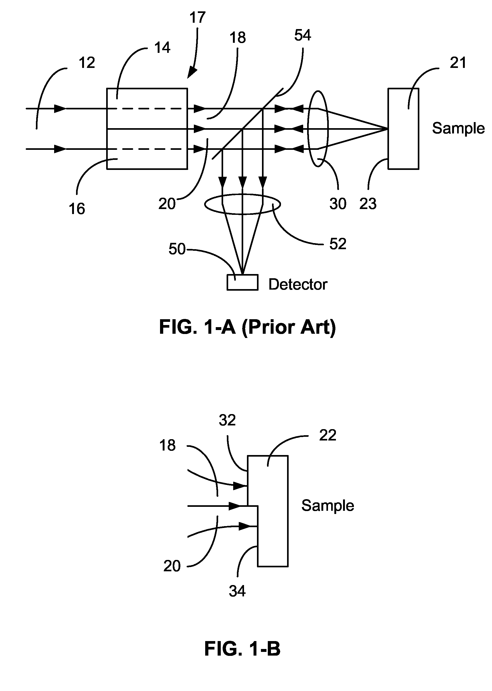
[0032] FIGS. 1-A and 1-B illustrate schematic cross-sectional views of a prior-art optical interferometric surface profiler. A collimated beam 12 is transmitted through regions 14 and 16 of a spatial phase modulator 17 and is divided into beam portions 18 and 20 by wavefront division. Next the beam portions are focused onto a surface 23 of a sample 21. The reflected beam from surface 23 is reflected by a beamsplitter 54 and focused onto a detector 50 by a focus lens 52.

[0033]FIG. 1-B shows a typical application of the device in FIG. 1-A. Beam portions 18 and 20 are focused onto a sample 22, where stepped surface areas 32 and 34 reflect the beam portions respectively. By tuning the phase difference between the two portions by modulator 17, the step height can be obtained. For example, the two portions can be tuned in or out of phase. Since how much the phase is tuned is known, the step height can be calculated.

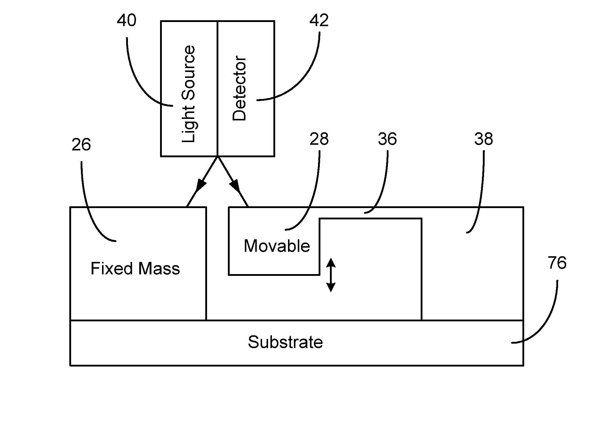
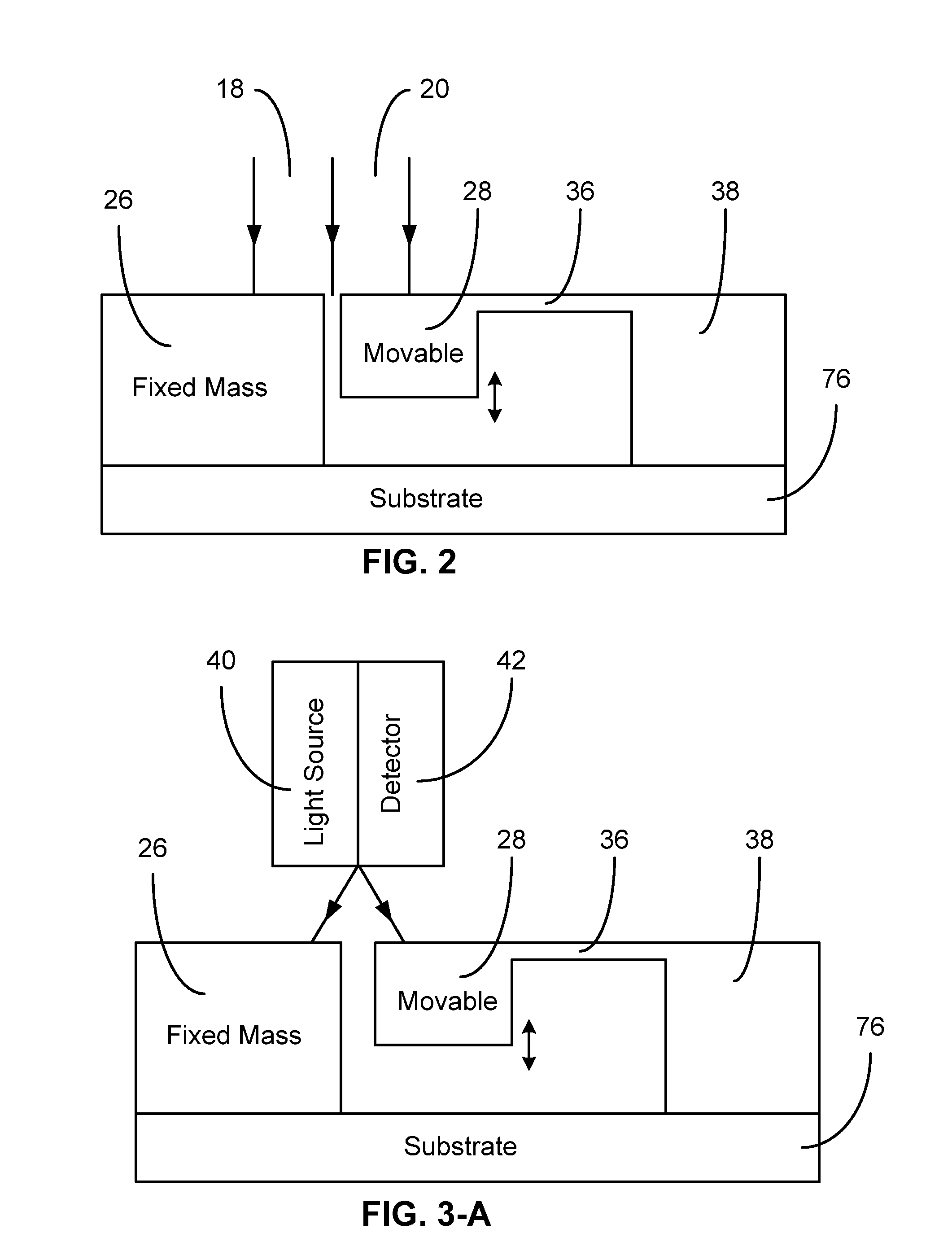
FIG. 2—Embodiment of a MOEMS Accelerometer

[...


PUM


Abstract

The present invention relates to an optical interferometric apparatus and method for measuring acceleration, pressure, and pressure of fluids during flow using micro-opto-electro-mechanical-systems (MOEMS). The high-sensitivity and high-resolution apparatus includes a movable mass, a stationary mass, a light source, and a photo detector. The light source emits a beam which is converted into two beam portions after impinging onto the movable and stationary masses. Interference between the beam portions are used to measure acceleration or pressure. The MOEMS structure may be integrated with a photo detector or planar waveguide. Differential amplification can be realized by employing two similar detecting structures.

Description

CROSS REFERENCE TO RELATED APPLICATION [0001] This application claims the benefit under 35 U.S.C. Sec. 119 of U.S. provisional patent application Ser. No. 60 / 648,423, filed Feb. 1, 2005, and U.S. provisional patent application Ser. No. 60 / 766,579, filed Jan. 30, 2006.FEDERALLY SPONSORED RESEARCH [0002] Not applicable SEQUENCE LISTING OR PROGRAM [0003] Not applicable BACKGROUND [0004] 1. Field of Invention [0005] This invention relates to optical interferometric sensors, particularly to interferometric MOEMS accelerometers and pressure sensors. [0006] 2. Description of Prior Art [0007] High-sensitivity and high-resolution accelerometers have applications in seismology and navigation. They are also used in monitoring systems of structure condition. In the applications, low cost and small size of an accelerometer are often required besides sensitivity and resolution. Among currently available methods for acceleration detection, e.g. capacitative, piezoresistive, piezoelectric, tunnelin...

Claims


Application Information

Patent Timeline
Patent Type & Authority Applications(United States)
IPC IPC(8): G01B11/02
CPCG01D5/266G01D5/268G01L9/0079G01P15/093G01V1/181
Inventor LI, CHIAN CHIU
Owner LI CHIAN CHIU
Why Eureka
Try Eureka