Projection optical system and projection display device using the same

a projection optical system and projection display technology, applied in the field of projection optical systems and projection display devices, can solve the problems of lateral color aberration in short focus optical systems, chromatic aberration, axial chromatic aberration, etc., and achieve the effects of easy assembly of the optical system, low manufacturing cost, and low distortion

Active Publication Date: 2006-08-31
FUJI PHOTO OPTICAL CO LTD
View PDF13 Cites 45 Cited by
  • Summary
  • Abstract
  • Description
  • Claims
  • Application Information

AI Technical Summary

Benefits of technology

[0009] The present invention relates to a high-performance, compact projection optical system and projection display device in which t

Problems solved by technology

However, when refractive optical systems are used as the projection optical systems, chromatic aberrations occur because of the characteristics of optical glass varying with wavelength.
Particularly, the axial chromatic aberration in long focal length optical systems, known as telescope-type optical systems, and the lateral color aberration in short focus optical systems is a major problem.
However, because at least three aspheric mirrors are used in the projection optical systems described in the above-mentioned Japanese laid-open patent application

Method used


Image

  • Projection optical system and projection display device using the same
  • Projection optical system and projection display device using the same
  • Projection optical system and projection display device using the same

Examples


embodiment 1

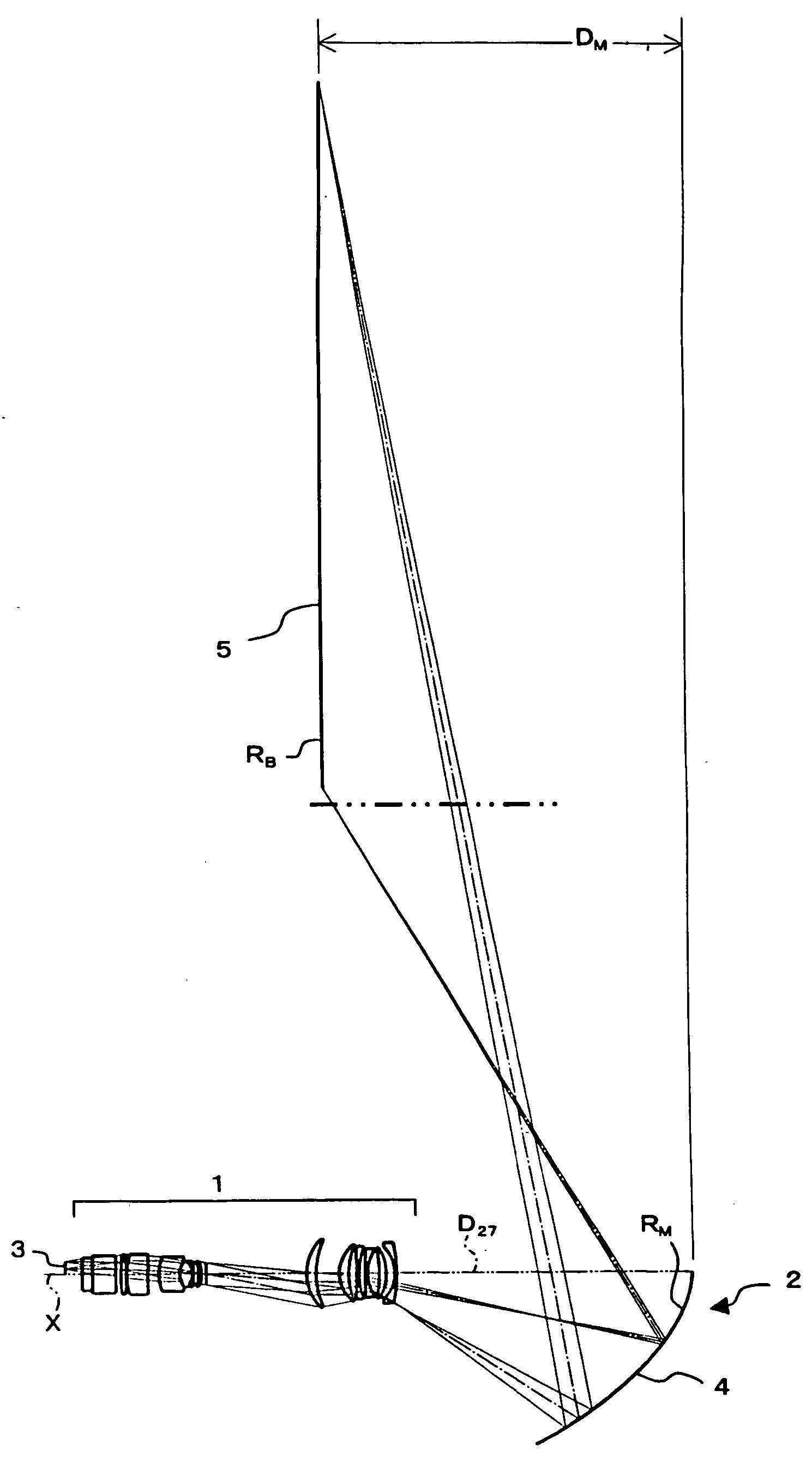
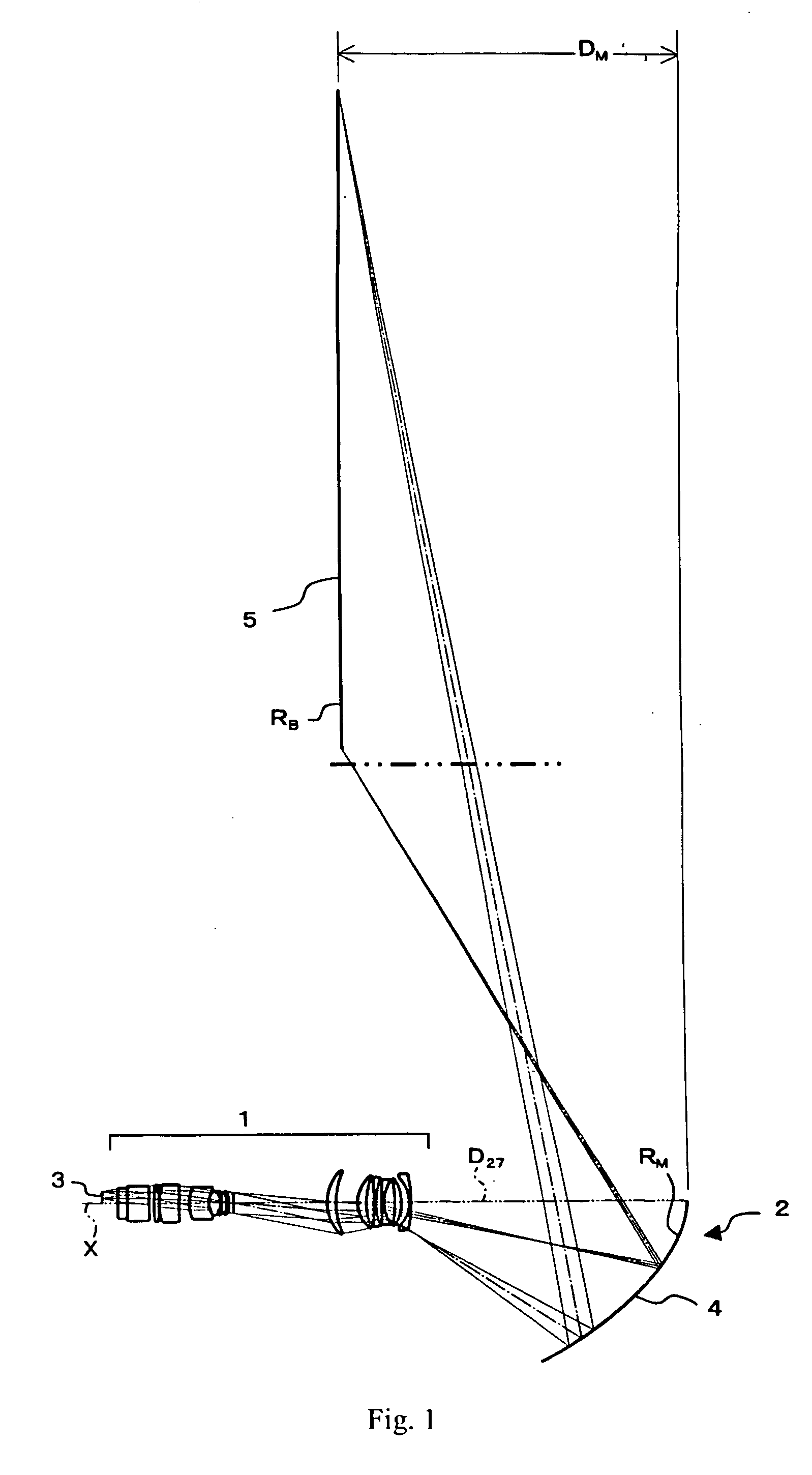
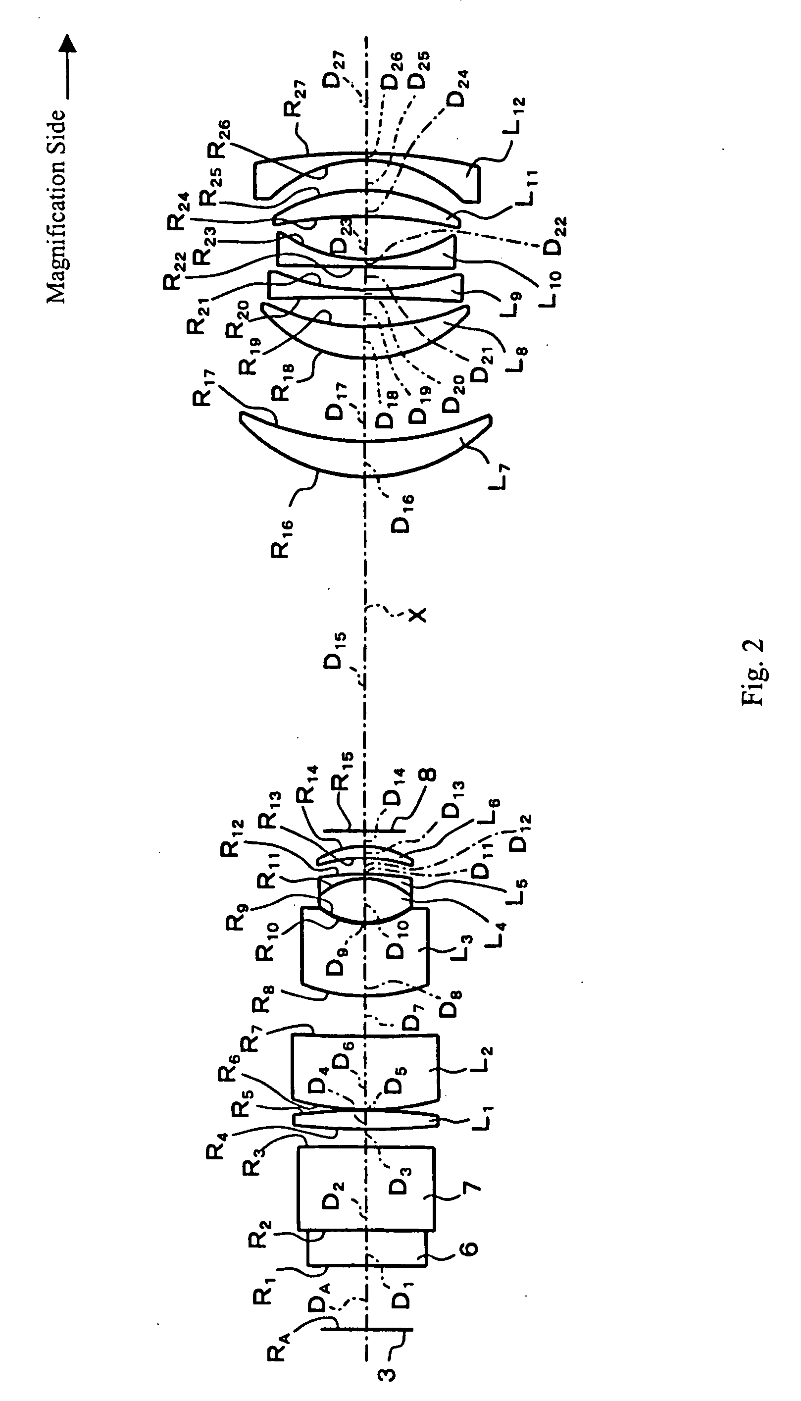
[0057]FIG. 1 shows a cross-sectional view of the projection optical system according to Embodiment 1 of the present invention. FIG. 2 shows an enlarged detailed view of the first imaging system of FIG. 1.

[0058] As shown in FIG. 2, the projection lens system, which is the first imaging system, transmits a light beam carrying image information provided by a light valve 3 formed as a reflective liquid crystal on silicon (LCOS) element. As shown in FIG. 1, the projection lens system 1 is on the reduction side of a mirror 4 which forms the second imaging system 2, and, as more clearly shown in FIG. 2, the projection lens system 1 includes, arranged in order from the reduction side, a cover glass 6, which is a plane parallel plate, a prism 7, a first group of six lens elements, L1-L6, a stop 8, and a second group of lens elements, L7-L12.

[0059] Here, the first lens element L1 is formed of glass with an Abbe number larger than eighty.

[0060] Table 1 below lists the surface number # in or...

embodiment 2

[0065]FIG. 3 shows a cross-sectional view of the projection optical system according to Embodiment 2 of the present invention. FIG. 4 shows an enlarged detailed view of the first imaging system of FIG. 3, and FIGS. 5A and 5B show a side view and a front view, respectively, of this embodiment. In FIGS. 3 and 4, the same symbols are attached to elements having the same effects as those of Embodiment 1 and a separate description of these elements is omitted.

[0066] The construction of this projection optical system is roughly the same as the projection optical system of Embodiment 1 but is different in ways. First, the second group of lens elements of the first imaging system 1 includes seven lens elements, L7-L13, and the seventh lens element L7 has negative refractive power, is formed of a resinous material, and is the closest lens element of the second group of lens elements to the stop 8, as shown in FIG. 4. Second, the second imaging system 2 is formed of three mirrors 9, 4, and 1...


PUM


Abstract

A projection optical system having a magnification side and a reduction side for forming a magnified image on a magnification side image surface conjugate with a reduction side conjugate image surface includes, arranged in order from the reduction side, a first imaging system including a plurality of lens elements and lens components and a second imaging system including a mirror having a concave, aspheric reflecting surface. An intermediate image is formed between the first imaging system and the second imaging system. The projection optical system satisfies specified conditions related to the travel of principal rays through the projection optical system and related to the Abbe number of a lens element having positive refractive power of the first imaging system. A projection display device includes the projection optical system and may include a light valve for modulating a light beam for projection on a screen.

Description

TECHNICAL FIELD OF THE INVENTION [0001] The present invention relates to a projection optical system and a projection display device, particularly a projection optical system for rear projection. BACKGROUND OF THE INVENTION [0002] Projection optical systems using a refractive optical system with refractive optical elements made of optical glass for projection display devices and projection televisions have been widely known. [0003] However, when refractive optical systems are used as the projection optical systems, chromatic aberrations occur because of the characteristics of optical glass varying with wavelength. Particularly, the axial chromatic aberration in long focal length optical systems, known as telescope-type optical systems, and the lateral color aberration in short focus optical systems is a major problem. [0004] An optical system formed as a single mirror has been proposed to eliminate such chromatic aberrations. Also, optical systems with a small number of mirrors, mor...

Claims


Application Information

Patent Timeline
IPC IPC(8): G02B23/00
CPCG02B13/0095G02B17/0856
Inventor SUZUKI, TAKASHI
Owner FUJI PHOTO OPTICAL CO LTD
Why Eureka
Try Eureka