Photonic bandgap fibers

a bandgap fiber and photonic technology, applied in the field of optical fibers, can solve the problem that the pulse cannot otherwise be guided over substantial distances in a conventional optical fiber, and achieve the effect of reducing transmission loss

Inactive Publication Date: 2006-08-31
IMRA AMERICA
View PDF6 Cites 74 Cited by
  • Summary
  • Abstract
  • Description
  • Claims
  • Application Information

AI Technical Summary

Benefits of technology

[0010] Included among the many structures described herein are photonic bandgap fibers designed to provide a desired dispersion spectrum. Additionally, designs for achieving wide transmission bands and lower transmission loss are also discussed.

Problems solved by technology

Such pulses may not otherwise be guided over substantial distances in a conventional optical fiber due to pulse distortion and / or energy loss from nonlinear processes in the core glass.

Method used


Image

  • Photonic bandgap fibers
  • Photonic bandgap fibers
  • Photonic bandgap fibers

Examples


examples

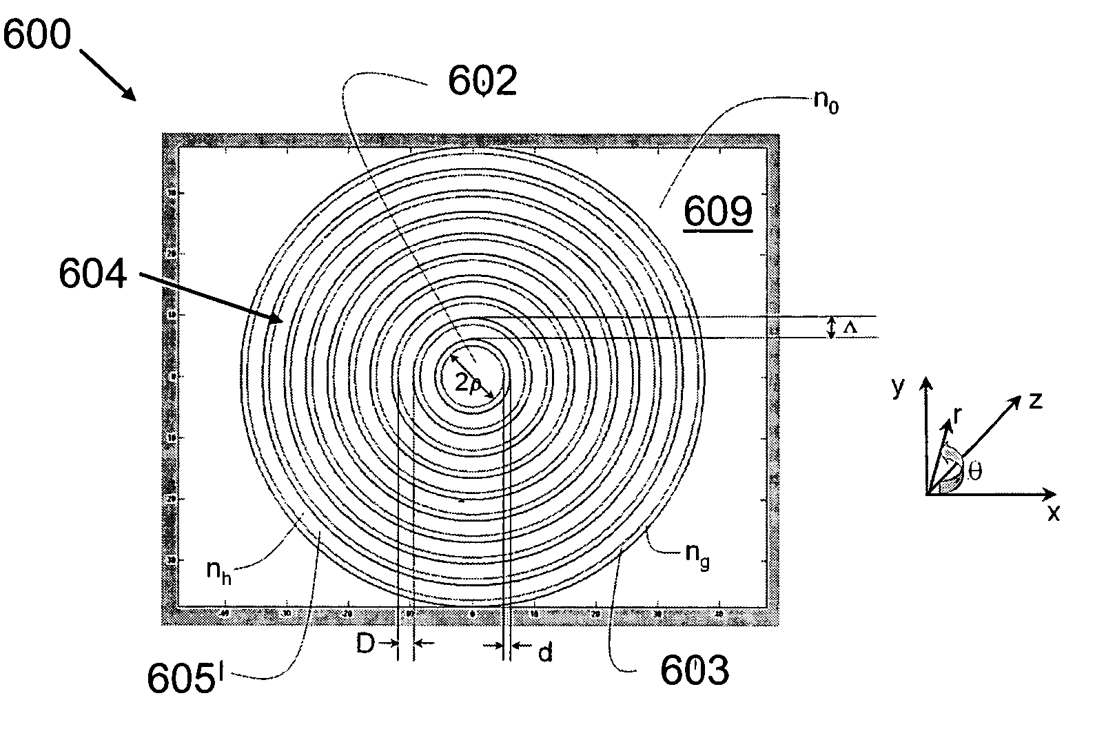
[0139] Any two dielectric media with different refractive indexes can be used to implement the fiber structures described herein. A suitable candidate for the high index material is glass, especially fused silica glass which is advantageous physical and optical properties, and durability. The low index medium can be chosen from one or a mixture of gases or vacuum. This choice of low index material has high nonlinear threshold, low scattering and absorption loss, and very low dispersion.

[0140] A PBGF with a wide transmission band has many applications, e.g. telecommunication and trace gas analysis based on spectral absorption or Raman scattering techniques. Such a broad transmission band can be achieved in Bragg fibers with νh2−nl2)1 / 2 and R<0.3. Wavelength scaling enables fiber designs for any wavelength range. The fiber dimension can be scaled proportionally to wavelength, i.e. double wavelength results in double fiber dimension.

[0141] Broad transmission band can also be achieved...


PUM

PropertyMeasurementUnit
widthaaaaaaaaaa
widthaaaaaaaaaa
thicknessaaaaaaaaaa

Abstract

Included among the many structures described herein are photonic bandgap fibers designed to provide a desired dispersion spectrum. Additionally, designs for achieving wide transmission bands and lower transmission loss are also discussed. For example, in some fiber designs, smaller dimensions of high index material in the cladding and large core size provide small flat dispersion over a wide spectral range. In other examples, the thickness of the high index ring-shaped region closest to the core has sufficiently large dimensions to provide negative dispersion or zero dispersion at a desired wavelength. Additionally, low index cladding features distributed along concentric rings or circles may be used for achieving wide bandgaps.

Description

PRIORITY APPLICATION [0001] This application claims priority to U.S. Provisional Patent Application No. 60 / 640,345 entitled “Dispersion Control in Photonic Bandgap Fibers” filed Dec. 30, 2004 (Attorney Docket No. IMRAA.032PR), which is incorporated herein by reference in its entirety.BACKGROUND [0002] 1. Field of the Invention [0003] This invention relates to optical fibers and more particularly to photonic bandgap fibers. [0004] 2. Description of the Related Art [0005] The concept of optical waveguides based on photonic bandgap (PBG) in periodic optical media was first proposed in a theoretical paper by Yeh and Yariv in 1978 (“Theory of Bragg Fibers”, Journal of Optical Society of America, vol. 68, no. 9, September 1978, pp. 1196-1201). Not until 21 years thereafter was the first practical demonstration of an optical fiber guided by the PBG effect reported in a paper by Cregan et al published in Science in September 1999 (R. F. Cregan, B. J. Mangan, J. C. Knight, T. A. Birks, P. St...

Claims


Application Information

Patent Timeline
Patent Type & Authority Applications(United States)
IPC IPC(8): G02B6/036G02B6/02H01J47/02H01J47/08G01T1/18H01J47/06G01N33/497G01N29/02G01N27/00G01N19/10G01N25/00
CPCC03B37/01205C03B37/01208C03B37/0122C03B2203/04C03B2203/12C03B2203/14C03B2203/16C03B2203/42G01N21/65G01N21/774G01N2021/655G02B6/02238G02B6/023G02B6/02304G02B6/02328G02B6/02338G02B6/02347G02B6/02357G02B6/02361G02B6/4206
Inventor DONG, LIANGPENG, XIANG
Owner IMRA AMERICA
Why Eureka
Try Eureka