
Film-Covered Battery And Fabrication Method

a technology of film-covered batteries and fabrication methods, which is applied in the direction of cell components, sustainable manufacturing/processing, cell components, etc., can solve the problems of short-circuiting with metal foils, reduced thickness of heat-seal resin layers, and the arrangement of resins does not achieve the anticipated effect, so as to facilitate the selective formation of cross-linked structures, reduce battery performance, and high reliability

Active Publication Date: 2006-08-31
NEC CORP
View PDF2 Cites 23 Cited by
  • Summary
  • Abstract
  • Description
  • Claims
  • Application Information

AI Technical Summary

Benefits of technology

[0012] It is an object of the present invention to provide: a film-covered battery that can prevent short-circuits between the battery element and metal foil that occur when sealing a battery element within laminate films composed of heat-seal resin layers and a metal foil layers due to melting of the heat-seal resin film at points of contact with the battery element that are caused by the heat applied at the time of heat-sealing; and to provide a fabrication method for such a battery.
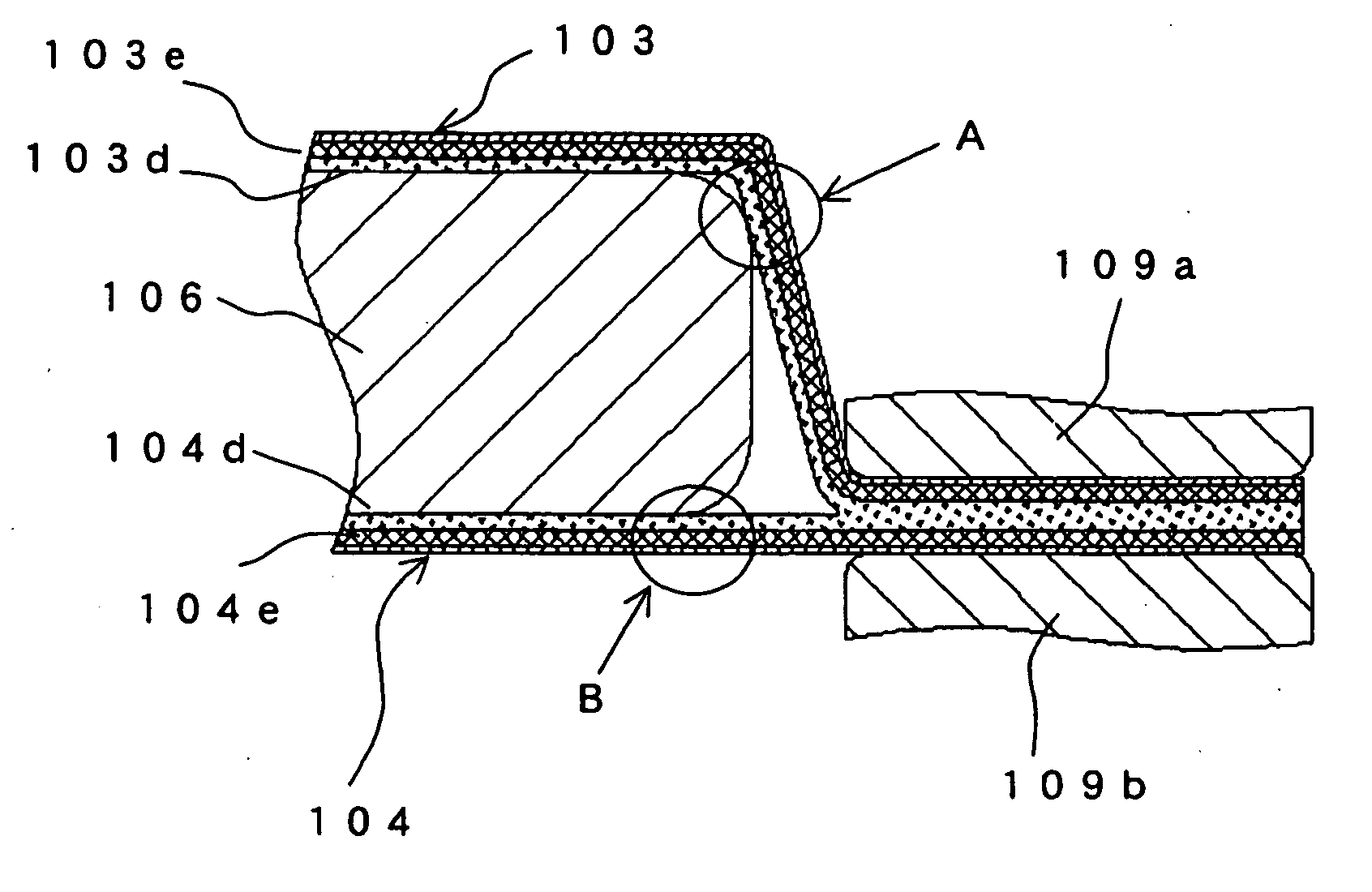
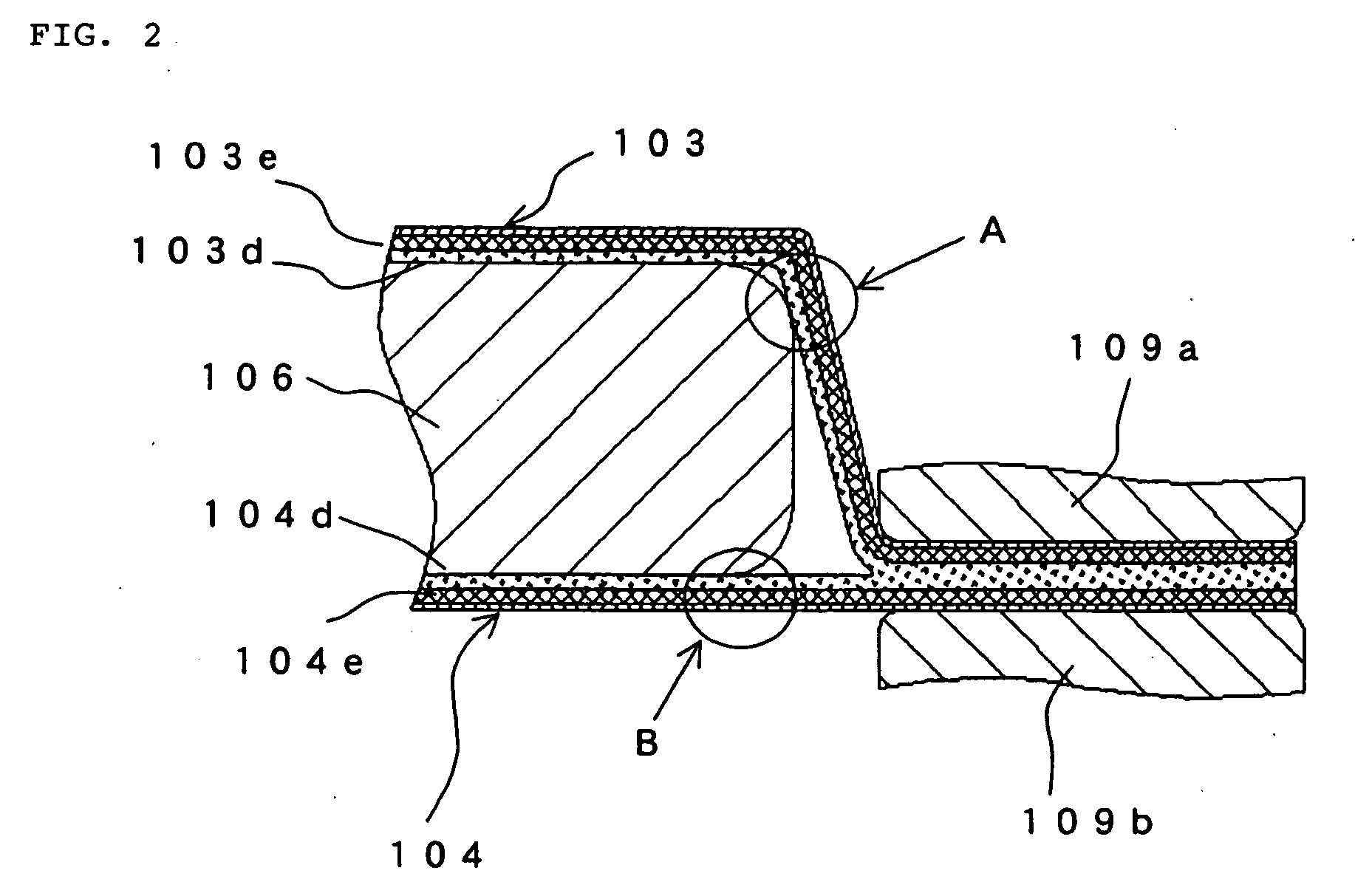
[0014] In the film-covered battery of the present invention, the cross-linked structure is formed in the heat-seal resin layer of the laminate film in the area in which the laminate film attains a temperature equal to or greater than the melting point at the time of heat sealing and in which the laminate film contacts with the part that is sealed inside. The heat resistance in the area in which the cross-linked structure is formed is therefore improved with respect to other areas, and as a result, the heat-seal resin layer is not melted by heat at the time of heat sealing, and short-circuits between the battery element and the metal foil layer are thus prevented. Further, because cross-linked structure is not formed in the outer periphery of the area that is heat-sealed, the laminate film is securely heat-sealed in area in which cross-linked structure is not formed and the battery element is therefore reliably sealed.
[0017] According to the fabrication method of the film-covered battery of the present invention, the cross-linked structure is formed only in specific area of the heat-seal resin of the laminate film, following which the laminate film is heat-sealed to seal the battery element, and as a result, as previously described, the sealing of the battery element by heat sealing of the laminate film can be performed reliably, and short-circuits between the battery element and metal foil layer at the time of heat-sealing the laminate film are prevented.
[0018] In the fabrication method of a film-covered battery according to the present invention, the step for forming the cross-linked structure preferably includes a step for masking an area of the laminate film in which the cross-linked structure is not to be formed and a step for irradiating the masked laminate film with an electron beam. This provision facilitates the selective formation of the cross-linked structure on the laminate film. The irradiation by electron beam is carried out before encapsulating the battery element in the laminate film, and the irradiation by the electron beam therefore does not cause a reduction in battery performance.
[0019] According to the present invention, a film-covered battery having high reliability can be obtained because short-circuiting does not occur between the battery element and metal foil at the time of heat sealing of the laminate film, and moreover, the heat-seal resin layer retain its natural property in area that is to be heat-sealed and suffer no reduction in heat-sealing ability, i.e., the ability to seal the battery element.

Problems solved by technology

However, the technique that is disclosed in JP-A-2001-126678 involves nothing more than increasing the thickness of portions of the heat-seal resin layer, and brings about no particular change regarding the melting of heat-seal resin in areas susceptible to short-circuiting that are in the vicinities of points that are heat-sealed when sealing the battery element.
Accordingly, if heat-seal conditions are not appropriately set according to the thickness of the layer of the heat-seal resin, either adequate heat-sealing may not be achieved, or conversely, excessive melting of the heat-seal resin may occur, resulting in the occurrence of short-circuiting with the metal foil.
As a result, in spite of the arrangement of heat-seal resin film for preventing short-circuits, the thickness of the layer of heat-seal resin has already been reduced by the deep-drawing process and the arrangement of resin therefore does not obtain the anticipated effect.

Method used


Image

  • Film-Covered Battery And Fabrication Method
  • Film-Covered Battery And Fabrication Method
  • Film-Covered Battery And Fabrication Method

Examples


Embodiment Construction

[0042] The following explanation regards an embodiment of the present invention with reference to the accompanying figures.

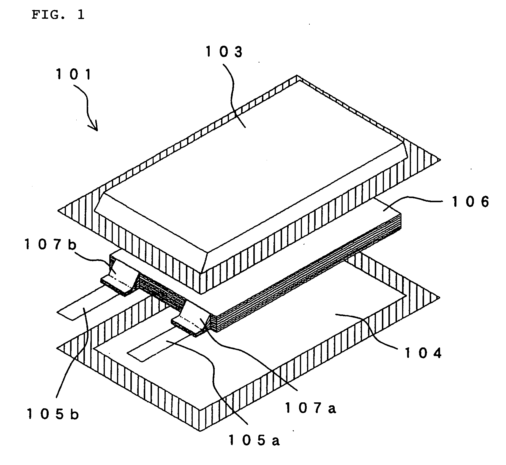
[0043] Referring to FIG. 3, an exploded view is shown of film-covered battery 1 according to an embodiment of the present invention. Film-covered battery 1 according to the present embodiment includes: battery element 6, positive electrode collector 7a and negative electrode collector 7b that are provided in battery element 6; an outer case for accommodating battery element 6 together with an electrolyte; positive electrode lead terminal 5a that is connected to positive electrode collector 7a; and negative electrode lead terminal 5b that is connected to negative electrode collector 7b.

[0044] Battery element 6 is made up from a plurality of positive electrode plates and a plurality of negative electrode plates, each of which is applied with an electrode material, that are alternately laminated with separators interposed. Each positive electrode plate and each n...


PUM

PropertyMeasurementUnit
temperatureaaaaaaaaaa
melting pointaaaaaaaaaa
areaaaaaaaaaaa

Abstract

A film-covered battery 1 includes battery element 6 and laminate films 3 and 4 for sealing battery element 6. Laminate films 3 and 4 are realized by laminating a heat-seal resin layer and a metal foil layer and seal battery element 6 by arranging the films on either side of battery element 6 with the heat-seal resin layers disposed on the inside and then heat-sealing at sealing areas 3a and 4a on the outer peripheries of the films. The areas of the laminate films 3 and 4 other than sealing areas 3a and 4a are electron beam irradiation areas 3b and 4b that are irradiated by an electron beam. Cross-linked structures are formed in the heat-seal resin layers of electron beam irradiation areas 3b and 4b by irradiation by an electron beam.

Description

TECHNICAL FIELD [0001] The present invention relates to a film-covered battery in which a battery element is incorporated in an outer covering composed of film, and to a method for fabricating the film-covered battery. BACKGROUND ART [0002] Recent years have witnessed a strong demand for lighter and thinner batteries as the power supplies of, for example, portable devices. The covering material of batteries has also come to employ materials such as metal foil and laminate films in which a metal foil and heat-seal resin film are laminated, and these films enable both lighter and thinner structures and greater freedom in the shapes that are adopted. [0003] A three-layer laminate film can be taken as a representative example of a laminate film that is used as the outer covering of a battery, this laminate film being formed by laminating heat-seal resin film, which is a heat-seal layer, on one side of an aluminum thin-film, which is the metal foil, and then laminating a protective film ...

Claims


Application Information

Patent Timeline
Patent Type & Authority Applications(United States)
IPC IPC(8): H01M2/08H01M2/06H01M10/04H01M50/119H01M50/121H01M50/124H01M50/136H01M50/178H01M50/55H01M50/553
CPCH01G9/016H01G9/10H01G9/155H01G11/74H01G11/80Y10T29/4911H01M2/021H01M2/0275H01M2/0287H01M2002/0297Y02E60/13H01G11/84Y02E60/10H01M50/131H01M50/124Y02P70/50H01M50/121H01M50/55H01M50/178H01M50/136H01M50/553H01M50/119H01M50/105H01M50/557H01G11/18H01M50/186
Inventor OTOHATA, MAKIHIROYAGETA, HIROSHI
Owner NEC CORP
Learn More