Cell measuring and sorting chip

a cell and chip technology, applied in the field of cell sorters, can solve the problems of difficult to distinguish the connecting cells to sort and detect cells, difficult to stably form the jet stream using the sheath, and high practical cos

Active Publication Date: 2006-08-31
JAPAN SCI & TECH CORP +1
View PDF7 Cites 47 Cited by
  • Summary
  • Abstract
  • Description
  • Claims
  • Application Information

AI Technical Summary

Benefits of technology

[0017] It is an object of the present invention to establish a cell sorting chip and a cell sorting technique for positively detecting and sorting a predetermined cell for...

Problems solved by technology

When such a phenomenon occurs in a cell sorter or a flow cytometer, it is difficult to distinguish those connecting cells to sort and detect the cells.
However, it is ...

Method used


Image

  • Cell measuring and sorting chip
  • Cell measuring and sorting chip
  • Cell measuring and sorting chip

Examples


first embodiment

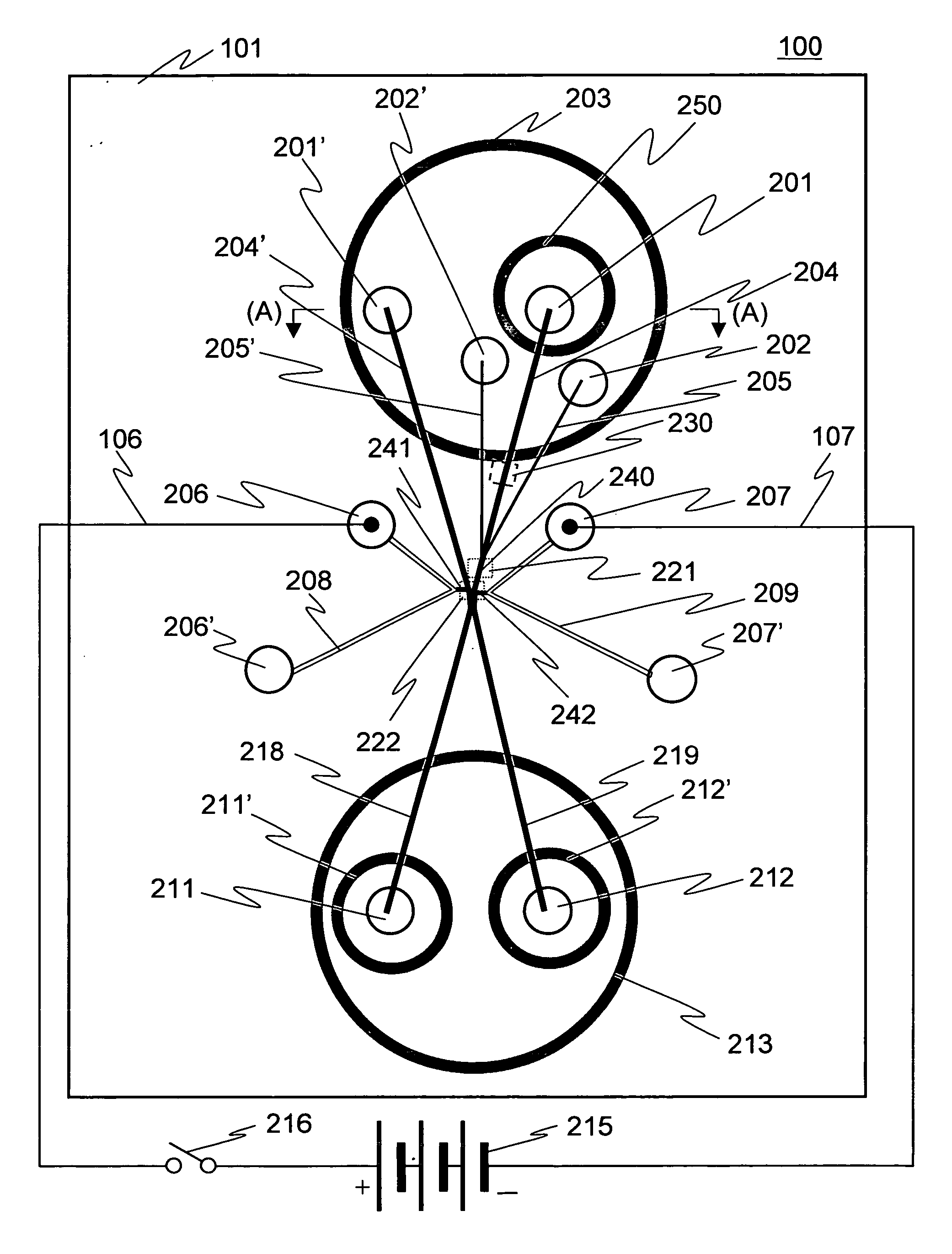
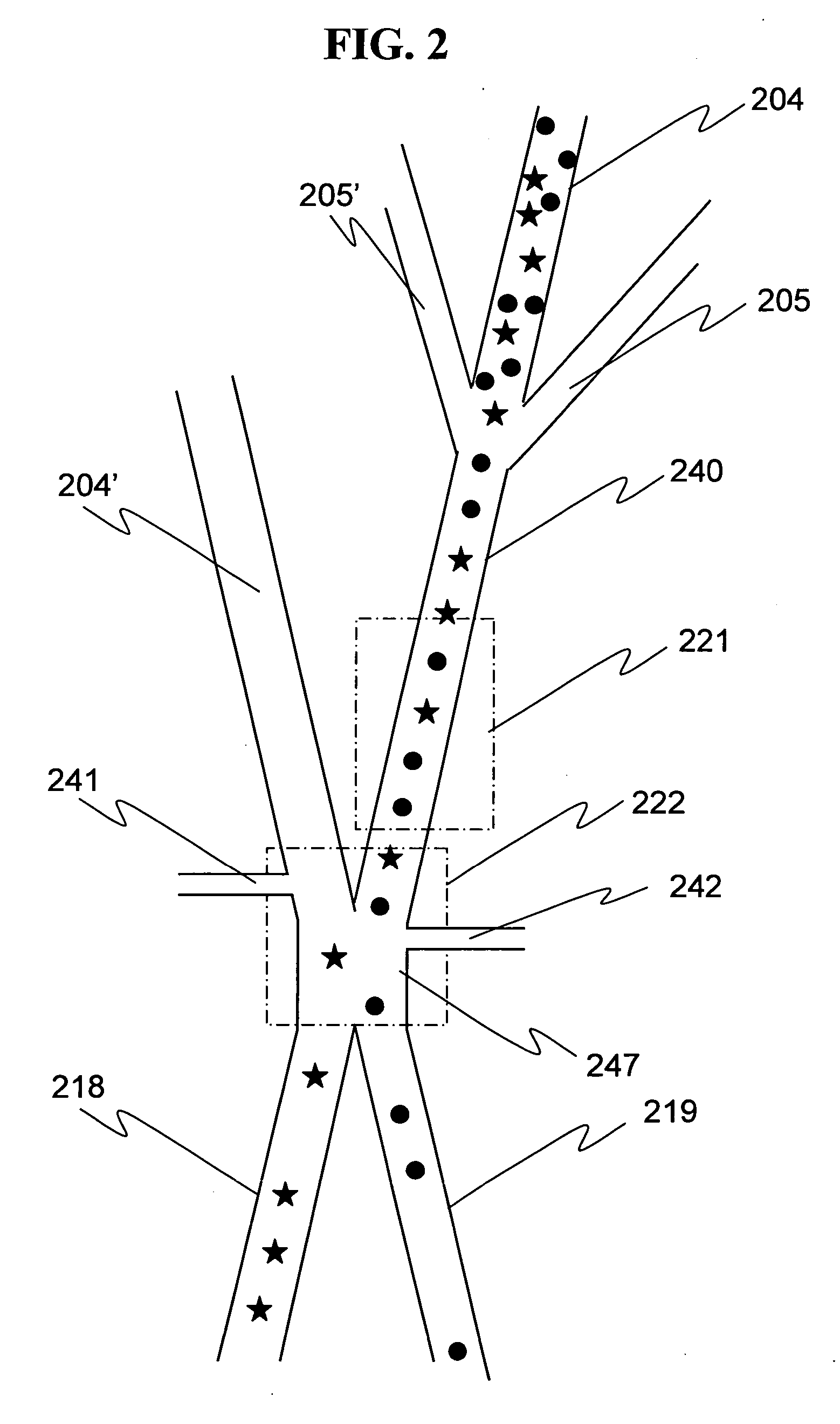
[0065]FIG. 1 is a plan view schematically showing one example of system configuration of a cell sorter according to the present invention. A cell sorter 100 includes a substrate 101. The substrate 101 has a flow path provided on the bottom surface and an opening communicating with the flow path provided on the top surface, and the opening functions as a port for supplying a sample or a necessary buffer fluid. Furthermore, a reservoir is provided for supplying a sufficient quantity of buffer fluid and also for controlling a flow rate in each flow path. The flow paths can be prepared by means of the so-called injection molding in which plastics such as PMMA is injected into a metal mold. The chip substrate 101 has the size of 20×30×1 mm (t) as a whole. To form grooves and through holes engraved on the bottom surface of the substrate 101 into flow paths and wells, a laminate film with a thickness of 0.1 mm is thermally applied to the bottom surface with the grooves engraved thereon. Ce...

second embodiment

[0081] A gel electrode is described in detail below. A gel electrode section includes holes 206, 206′ and 207, 207′, a microstructure 208 connecting the holes 206, 206′ to each other, a microstructure 209 connecting the holes 207, 207′ to each other, and coupling sections 241, 242 based on a structure allowing liquid communication in the cell sorting region 222, as shown in FIG. 1. When a chip is prepared by means of injection molding, no gel is included in the gel electrode section. The following description assumes use of agarose gel containing an electrolyte as an electrolytic solution. The gel is prepared such that a 0.25M NaCl-0.296M sodium phosphate (pH 6.0) buffer fluid is used for forming the minus electrodes 209, 242, and 1% agarose gel containing 0.25M NaCl-0.282M sodium phosphate (pH 8.0) is used for forming the plus electrodes 208, 241. The pH is differentiated to prevent generation of bubbles in association with electrolysis when a current is supplied. Hydrogen ions gen...

third embodiment

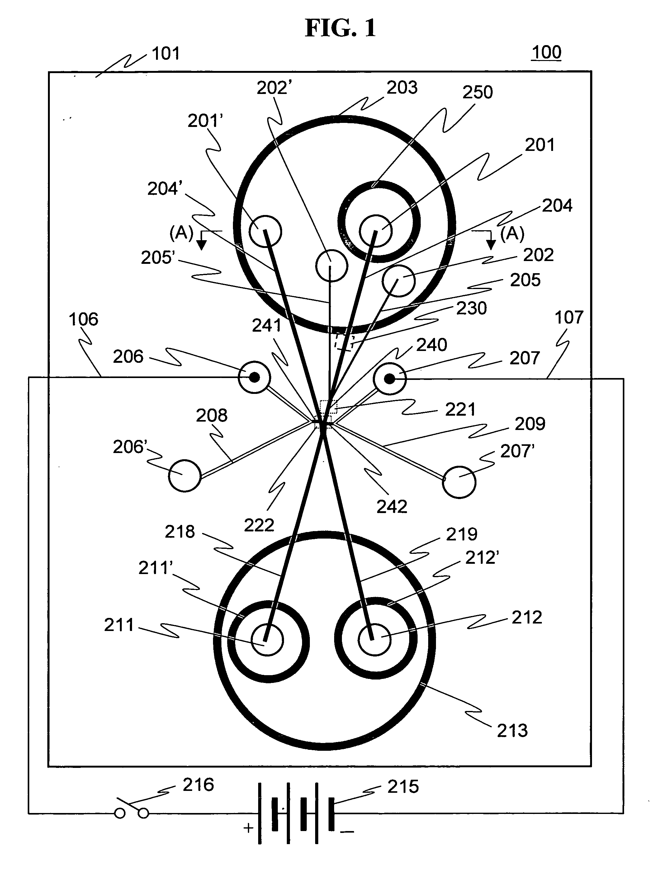
[0097] An algorithm for recognizing and sorting cells by means of image recognition using the cell sorter chip 100 shown in FIG. 1 is described below. As described with reference to FIG. 1, the cell suspension is injected into the hole 201. A wall 250 for preventing diffusion of the cell suspension is provided around the hole 201. The wall 250 is prepared in the reservoir 203, and a liquid surface in the hole 201 is equal to that in the reservoir 203. The cells flow from the hole 201 to the flow path 204, and join together with the flow path 205 constituting a side flow at a position just ahead the cell detecting area 221. Because of the join, the state where the cells are concentrated toward a central portion of the flow path can be realized. Refer to FIG. 3.

[0098] Images of the cells passing over the cell detecting area 221 in the flow path 204 are picked up with a CCD camera. A CCD camera capable of picking up 200 frames per second can be used for this purpose. With this image p...


PUM


Abstract

The present invention provides a cell sorting device using an inexpensive chip capable of being exchanged for each sample for cell sorting. The cell sorting device uses flow paths formed on the substrate and has the following structure. The chip includes: a first flow path allowing a buffer fluid containing cells to flow down; second and third flow paths which put the first flow path therebetween and allow a buffer fluid not containing cells to flow down from both sides of the first flow path; a fourth flow path which allows the buffer fluid as a single flow path formed by the join of the buffer fluid in the first flow path and the buffer fluid in the second and third flow paths; a cell detecting region for detecting cells flowing with a buffer fluid down the fourth flow path; a cell sorting region for sorting the cells according to a type of the cells detected. The first flow path, the second and the third flow paths, the fourth flow path, the cell detecting region and the cell sorting region provided in a cascade. Two flow paths are provided to allow the cells sorted to flow downstream of the cell sorting region. The buffer fluid flowing in the first to the fourth flow paths is supplied from reservoirs having the same fluid level. The first flow path and the fourth flow path are structured to have substantially the same width or cross-section area.

Description

FIELD OF THE INVENTION [0001] The present invention relates to a cell sorter. BACKGROUND OF THE INVENTION [0002] An anatomy of a multicellular organism retains a harmonious function as a whole by each cell taking a separate role. Otherwise, when part of the cells becomes cancerous (hereinafter referred to as a cancer, including tumors), the part grows into a neoplasm different from its peripheral region. However, the cancerous region and a normal tissue region away therefrom may not necessarily be sorted by a certain borderline, that is, the region surrounding the cancer is affected in some way. In order to analyze a function of an organ tissue, therefore, it is necessary to sort a small number of cells present in a small region. [0003] Otherwise, in the medical field, in order to examine a region suspected of a cancer in the normal tissue, it is necessary to sort the region suspected of the cancer from a piece of tissue sorted in biopsy. For separation of such specific cells, it is...

Claims


Application Information

Patent Timeline
IPC IPC(8): C12M1/34B07C5/00
CPCB01L3/502761B01L2200/0647B01L2300/0681B01L2300/0816B01L2300/0864B01L2400/0415B01L2400/0487G01N15/147G01N35/085G01N2015/149G06T7/0012G06T2207/10056G06T2207/30024C12M47/04
Inventor YASUDA, KENJIHATTORI, AKIHIROOKANO, KAZUNORI
Owner JAPAN SCI & TECH CORP
Why Eureka
Try Eureka