
Method and system for the derivation of human gait characteristics and detecting falls passively from floor vibrations

a technology of human gait and vibration, applied in the field of human gait characteristics and vibration detection, can solve the problems of impracticality of longitudinal in-home gait monitoring using these technologies, high equipment requirements for functional gait laboratories, and major morbidity in the elderly. , to achieve the effect of heightened fall risk

Inactive Publication Date: 2006-08-31
UNIV OF VIRGINIA ALUMNI PATENTS FOUND
View PDF11 Cites 109 Cited by
  • Summary
  • Abstract
  • Description
  • Claims
  • Application Information

AI Technical Summary

Benefits of technology

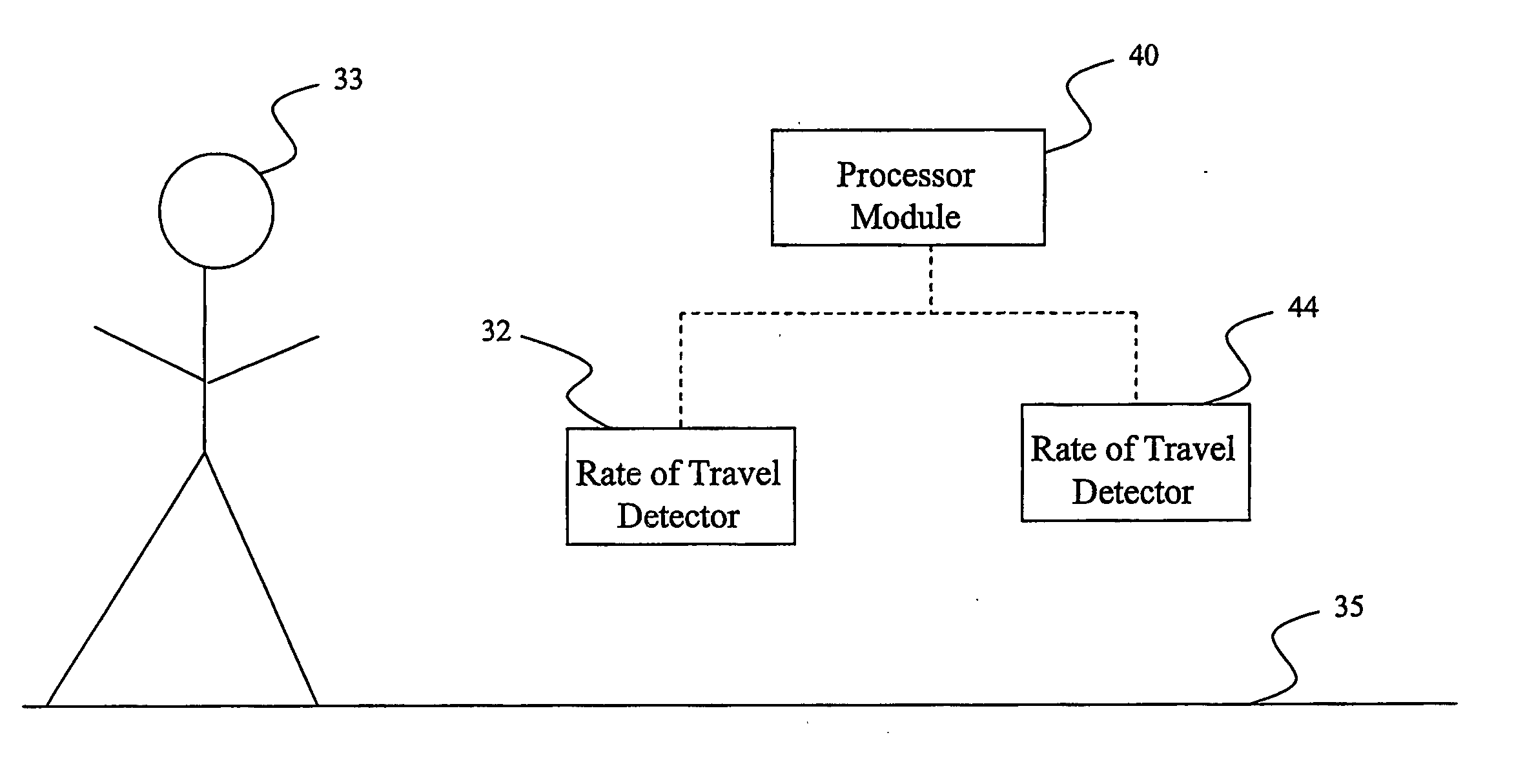
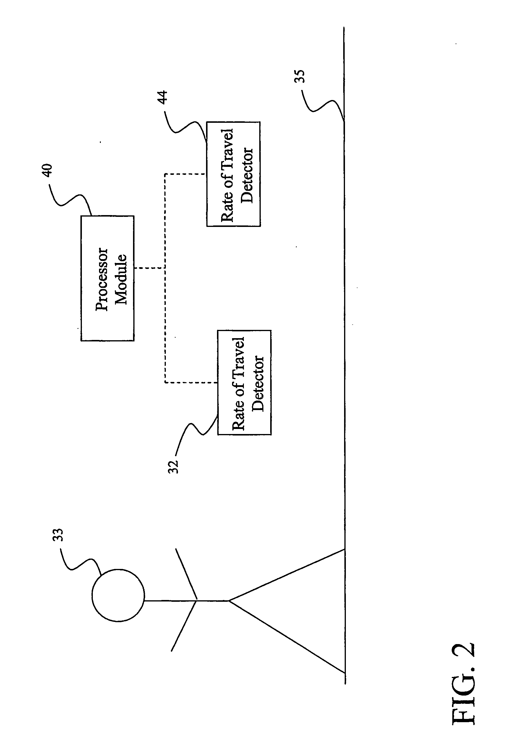
[0007] The present invention passive gait monitor system and method described in this disclosure are based on detecting vibrations generated by a person or animal walking on the floor. An embodiment is implemented using an ultra sensitive optic-fiber sensor that is capable of tens of feet away from the sensor on both carpeted and uncarpeted wooden and concrete floors. However, the methods described can be applied to other vibration, acceleration, and / or deflection sensors and sensing technologies, including but not limited to piezoelectric, electromechanical, optic, laser, and fiber optic sensors. The vibration, acceleration, and / or deflection sensor can be fixed in a corridor or a walkway within the home environment or any desired environment, for short term and extended term monitoring of changes in gait mode and drifts in cadence that may indicate a heightened fall risk, as well as actual fall. Since it can be deployed in natural settings and the user does not need to wear any devices, walk on special surfaces or be observed by cameras, this gait monitor is completely passive and unobtrusive; hence, the “white coat” stress effect associated with a clinical test could be reduced or even totally eliminated.
[0009] Other applications include unobtrusive gait analysis in clinical settings. One can envision the deployment of such a monitor in a corridor within the clinic, where a person's gait is preliminarily evaluated as he / she enters the clinic and that the analysis report is available to the clinician by the time the patient walks into the examination room. Longitudinal data, together with more elaborate analysis techniques lead to a fall prediction model. Other data may include, for example, pattern recognition or identification determination of the subject (human or animal) being monitored. An embodiment of the sensing unit of the passive gait monitor is physically small, low-cost, and designed to transmit acquired data via hardwired or wireless means. Thus, this embodiment of this passive gait monitor may be ideally suited to monitoring the ‘natural gait’ of a person during regular activity, in the home or in the clinic, to provide basic but essential gait characteristics.

Problems solved by technology

On the other hand, falls are a major cause of morbidity in the elderly.
However, the equipment required for a functional gait laboratory is extremely expensive, in the range of tens of thousands to a few hundred thousand dollars in equipment and software.
Additionally, the computational power required for the image based analysis make longitudinal in-home gait monitoring using these technologies impractical.
Moreover, accelerometers do not provide enough information to enable the evaluation of the actual characteristics of the gait.
Another potential method for gait analysis is to have a ‘smart floor’ comprising force plate tiles or embedding load cells under individual tiles (See Orr R, Abowd G., “The Smart Floor: A Mechanism for Natural User Identification and Tracking Conference on Human Factors in Computing Systems,” April 2000, of which is hereby incorporated by reference herein in its entirety.) to measure characteristics of footsteps; this approach is expensive.

Method used


Image

  • Method and system for the derivation of human gait characteristics and detecting falls passively from floor vibrations
  • Method and system for the derivation of human gait characteristics and detecting falls passively from floor vibrations
  • Method and system for the derivation of human gait characteristics and detecting falls passively from floor vibrations

Examples


example no.1

EXAMPLE NO. 1

[0036] FIGS. 3(A)-(B) are schematic plan and elevation views, respectively, of an embodiment of the present invention acceleration, vibration, and / or deflection module 32. Provided is an embodiment of the present invention acceleration, vibration, and / or deflection module 32 that detects floor acceleration, vibration, and / or deflection to provide acceleration, vibration, and / or deflection signal. The gait sensor 32 transduces the displacement of the floor surface 95 into a waveform signal which can be retained and analyzed. The design employs a linear variable differential transformer (LVDT) 92. The LVDT 92 may also be any low mass, high resolution displacement sensor technology including but are not limited to magnetic coil induction; laser light reflection; changes in Plasmon surface resonance; RF; changes in light due to luminescence; doppler radar; and / or any sensor technology that transduces the minute deflections of the floor induced by gait or falling or dropping...

example no.2

EXAMPLE NO. 2

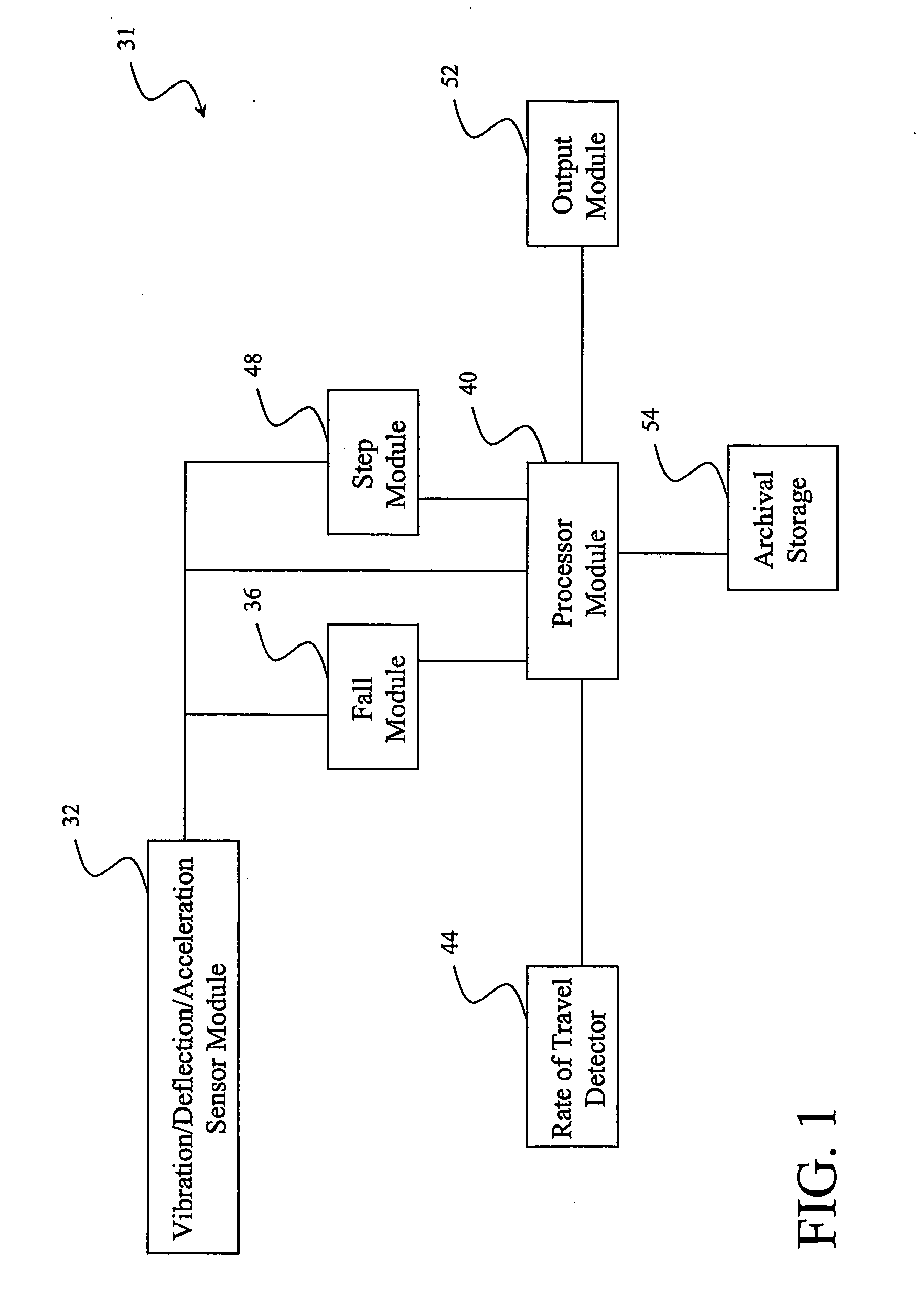
[0038] Referring to FIG. 4, FIG. 4 illustrates a schematic a block diagram of an example of an embodiment of the present invention system 61. In the current embodiment, the fall detection is a separate entity from the step counter 78, which allows the calculation of cadence, and from the limp detector 74 and shuffle detector 72. The fall detector consists of a second order Butterworth band-pass filter (about 30 Hz-50 Hz) 62. This filter was tuned to block frequencies generated by different walk modes or dropped objects and to yield the highest output in response to falling people. However, it should be appreciated that other filter designs, including filter type, order and frequencies, may yield similar results. The filter output feeds into an amplifier and comparator 70 to detect falls; the comparator threshold is tuned to detect a low weight human falling about ten feet (or as desired) from the sensor, yet remain insensitive to dropped objects. This reduces potential ...

example no.3

EXAMPLE NO. 3

[0041]FIG. 5 shows a graphical representation of an example of the results obtained applying an exemplary circuit model to the data obtained from the floor vibration sensor for a normal walk. FIG. 6 shows a graphical representation of an example of the results obtained applying an exemplary circuit model to the data obtained from the floor vibration sensor for a limp. FIG. 7 shows a graphical representation of an example of the results obtained applying an exemplary circuit model to the data obtained from the floor vibration sensor for a shuffle. FIG. 8 shows a graphical representation of an example of the results obtained applying an exemplary circuit model to the data obtained from the floor vibration sensor for a fall.

[0042] Turning to FIG. 5, shows FIG. 5 the graphically shows the signals generated by a person walking in a normal gait mode, together with the derived signals throughout the various processing stages in our circuit model. Knowing the location of the s...


PUM


Abstract

The gait monitor system and method provides various basic gait parameters including step count, cadence, and step duration, in addition to its ability to distinguish between normal, limping and shuffling gait modes, as well as determine falls. Moreover, this gait monitor may be provided with additional sensors, e.g. beam break at the beginning and end of a corridor to estimate average walking velocity (with the distance between the beams known or determined); this enables the calculation of additional gait characteristics such as average step length and average stride length. These parameters can additionally be used to detect various gait anomalies and other diagnostic information.

Description

RELATED APPLICATIONS [0001] This application claims priority under 35 U.S.C Section 119(e) of the earlier filing date of U.S. Provisional Application Ser. No. 60 / 460,237, filed on Apr. 3, 2003, entitled “Method and System for the Derivation of Basic Human Gait Characteristics and Detecting Falls Passively from Floor Vibrations,” of which the entire disclosure is hereby incorporated by reference herein.BACKGROUND OF THE INVENTION [0002] Gait analysis has many applications ranging from rehabilitation to sports medicine, orthopedics and studying the effectiveness of prosthetics to improve their design. See Joseph C, Andrew G., “Gait Analysis in the Amputee: Has it Helped the Amputee or Contributed to the Development of Improved Prosthetic Components?” Gait Posture (1996) 4, 258-68, of which is hereby incorporated by reference herein in its entirety. Long-term in-home gait monitoring not only can provide a measure of a person's functional ability, but it also can provide a measure of ac...

Claims


Application Information

Patent Timeline
IPC IPC(8): A61B5/103A61B5/00G01P3/50
CPCA61B5/0002A61B5/0017A61B5/1038A61B5/1117A61B2562/02A61B2562/0219G01P3/50G06K9/00335G06F2218/00G06V40/20
Inventor ALWAN, MAJDFELDER, ROBIN A.KELL, STEVEN W.DALAL, SIDDHARTH
Owner UNIV OF VIRGINIA ALUMNI PATENTS FOUND
Learn More