Stent for implantation in a blood vessel, especially in the region of the aortic arch

a blood vessel and aortic arch technology, applied in the field of stents for implantation in blood vessels, can solve the problems of insufficient fixing and unsuitable treatment of mesh-type stents, and achieve the effect of improving the stability of the stent and enhancing the stability of the flank

Active Publication Date: 2006-08-31
JOTEC
View PDF14 Cites 35 Cited by
  • Summary
  • Abstract
  • Description
  • Claims
  • Application Information

AI Technical Summary

Benefits of technology

[0015] An advantage of this embodiment is that it is not the entire jacket area between the last ring and the penultimate ring that is designed without prosthesis material. This makes it possible, on the inside wall of the aortic arch directed away from the origins of the arteries of the head, to provide prosthesis material and thus a jacket area which is used not only for support purposes but also as a sealing surface. By means of the V-shaped design of the connecting support, it is particularly easy to produce the jacket area free of prosthesis material and widening in a wedge shape toward the proximal end of the stent. The jacket is removed in the area of the wedge-shaped jacket area, and the resulting edges of the prosthesis material are affixed to the V-shaped struts of the connecting support.
[0050] These measures are known from the prior art; they permit rapid and inexpensive but reliable production of the novel stent.

Problems solved by technology

A mesh-type stent of this kind is not suitable for treatment of aneurysms in the region of the descending aorta.
Although a simple beveling at the proximal end of the stent lying in the aortic arch also permits supply of blood to the branching-off arteries, it does not permit sufficient fixing.

Method used


Image

  • Stent for implantation in a blood vessel, especially in the region of the aortic arch
  • Stent for implantation in a blood vessel, especially in the region of the aortic arch
  • Stent for implantation in a blood vessel, especially in the region of the aortic arch

Examples


Embodiment Construction

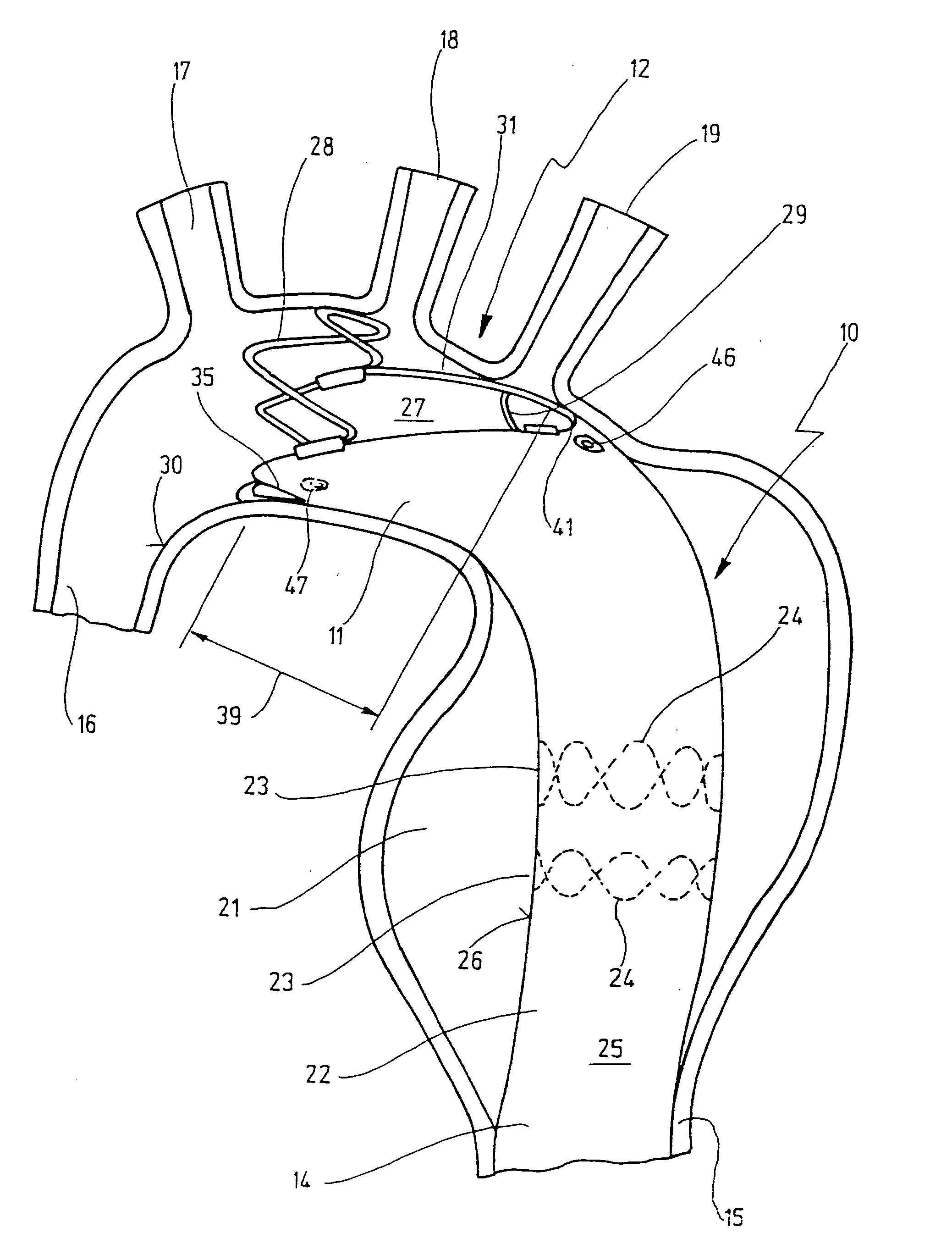
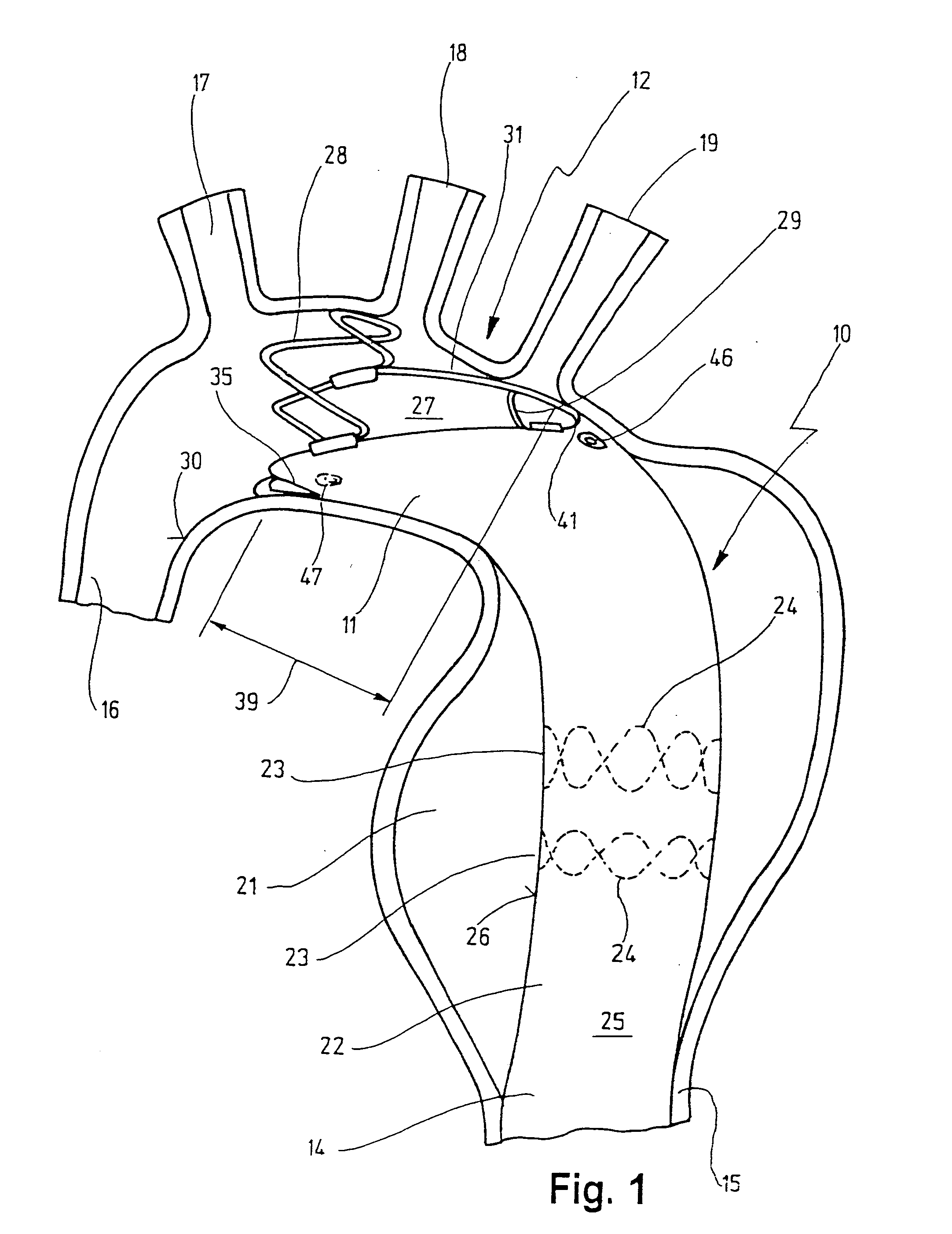
[0065] In FIG. 1, reference number 10 designates a stent which is anchored with its proximal end 11 in the aortic arch 12 and with its distal end 14 in the descending aorta 15.

[0066] Before the stent 10 is described in detail, the aortic system also shown schematically in FIG. 1 will first be explained.

[0067] The ascending branch 16 of the aorta (aorta ascendens) is connected, via the aortic sinus (not shown in FIG. 1), to the left ventricle of the heart (also not shown in FIG. 1). The ascending aorta 16 is connected to the descending aorta 15 via the aortic arch 12. Arterial vessels of the head have their origin in the region of the aortic arch 12, namely the brachiocephalic trunk 17, the common carotid artery 18 and the left subclavian artery 19.

[0068] Reference number 21 designates an aneurysm located in the descending aorta 15 and bridged, as it were, by the stent 10. The blood flow from the ascending aorta 16 passes through the aortic arch 12 into the proximal end 11 of the ...


PUM


Abstract

A stent for implantation in a blood vessel is disclosed, especially in the region of the aortic arch. The stent is comprising rings which are disposed successively in the stent's longitudinal direction and which are made up of meandering circumferential supports. The stent further comprises a prosthesis material which is fixed to the rings and which connects them, thereby forming a hollow cylindrical body with a jacket which is substantially closed on the circumference thereof. At least one connecting support is provided between the last ring and the penultimate ring at the proximal end of the stent and connects these two rings to one another.

Description

CROSS-REFERENCE TO RELATED APPLICATIONS [0001] This is a continuation application of International Patent Application PCT / EP2004 / 008916, filed on Aug. 10, 2004, designating the United States and published in German as WO 2005 / 013854 A1, which claims priority to German application number 103 37 739.5, filed on Aug. 12, 2003. The contents of these documents are incorporated herein by reference.TECHNICAL FIELD [0002] The present invention relates to a stent for implantation in a blood vessel, especially in the region of the aortic arch, with rings which are disposed successively in its longitudinal direction and which are made up of meandering circumferential supports, and with a prosthesis material which is fixed to the rings and which connects them, said prosthesis material forming a hollow cylindrical body with a jacket which is substantially closed on the circumference. [0003] These endovascular stents are implanted for treatment of aneurysms in arteries. An aneurysm is understood ...

Claims


Application Information

Patent Timeline
Patent Type & Authority Applications(United States)
IPC IPC(8): A61F2/06A61F2/07A61F2/82A61F2/856A61F2/86A61F2/88
CPCA61F2/07A61F2/856A61F2/86A61F2002/075A61F2002/061A61F2002/828A61F2/89A61F2/88
Inventor KAUFMANN, RALFLESMEISTER, RAINERMULLER, HARDYBRAUN, MICHAELGEIS, JOHN
Owner JOTEC
Why Eureka
Try Eureka