Vehicle cooling system

a technology for cooling systems and vehicles, applied in the direction of lighting and heating apparatus, process and machine control, instruments, etc., can solve the problems of poor thermal shock performance, and heat exchangers will undergo thermal shock, so as to increase the weight and increase the cost

Active Publication Date: 2006-09-07
NISSAN MOTOR CO LTD +1
View PDF5 Cites 35 Cited by
  • Summary
  • Abstract
  • Description
  • Claims
  • Application Information

AI Technical Summary

Benefits of technology

[0013] Meanwhile, the heat exchanger disclosed in Japanese Laid-Open Patent Publication No. 2004-293982 mentioned above requires the structure of the heat exchanger to be strengthened in order to make it resistant to thermal shock, which introduces the additional problems of increased c

Problems solved by technology

The problem with such conventional vehicle cooling system is that when the coolant temperature at the outlet of the vehicle unit becomes high, the three-way valve is immediately switched to the heat exchanger position to open the coolant route that directs the coolant through the heat exchanger.
If a difference between the coolant temperature at the outlet of the vehicle unit and the coolant temperature inside the heat exchanger is large, the heat exchanger will undergo thermal shock.
Particularly in the case of a fuel cell vehicle that operates at high efficiency, the hea

Method used


Image

  • Vehicle cooling system
  • Vehicle cooling system
  • Vehicle cooling system

Examples


second embodiment

[0053] Referring now to FIGS. 4 and 5, a second embodiment of the present invention will now be explained. In view of the similarity between the first and second embodiments, the parts of the second embodiment that are identical to the parts of the first embodiment will be given the same reference numerals as the parts of the first embodiment. Moreover, the descriptions of the parts of the second embodiment that are identical to the parts of the first embodiment may be omitted for the sake of brevity.

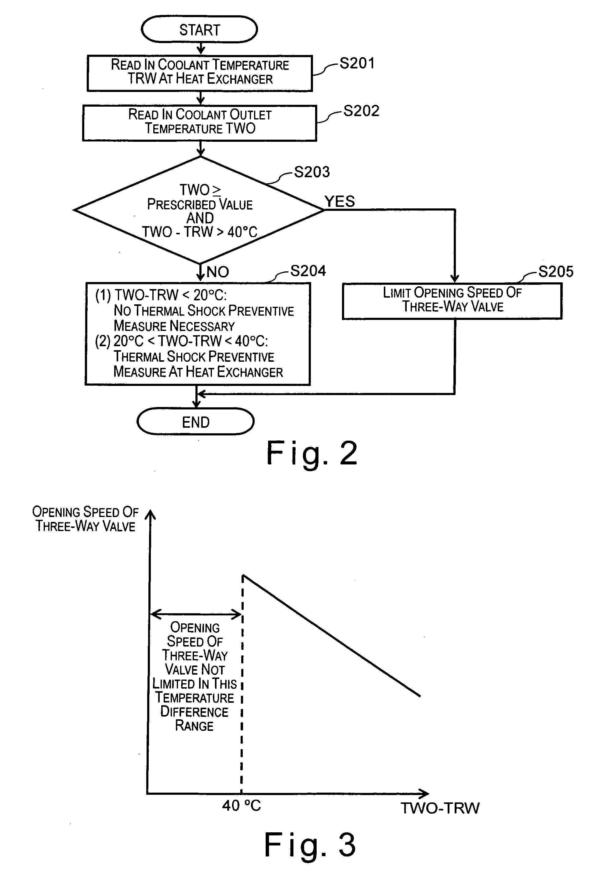
[0054] The second embodiment of the present invention is basically identical to the first embodiment except for the control process executed in the controller 12. More specifically, the control process in accordance with the second embodiment is identical to the control process in accordance with the first embodiment illustrated in the flowchart of FIG. 2 except that an additional control is executed after step S205 of FIG. 2. Thus, the constituent components of the vehicle cooling sys...

third embodiment

[0064] Referring now to FIG. 6, a third embodiment will now be explained. In view of the similarity between the first and third embodiments, the parts of the third embodiment that are identical to the parts of the first embodiment will be given the same reference numerals as the parts of the first embodiment. Moreover, the descriptions of the parts of the third embodiment that are identical to the parts of the first embodiment may be omitted for the sake of brevity.

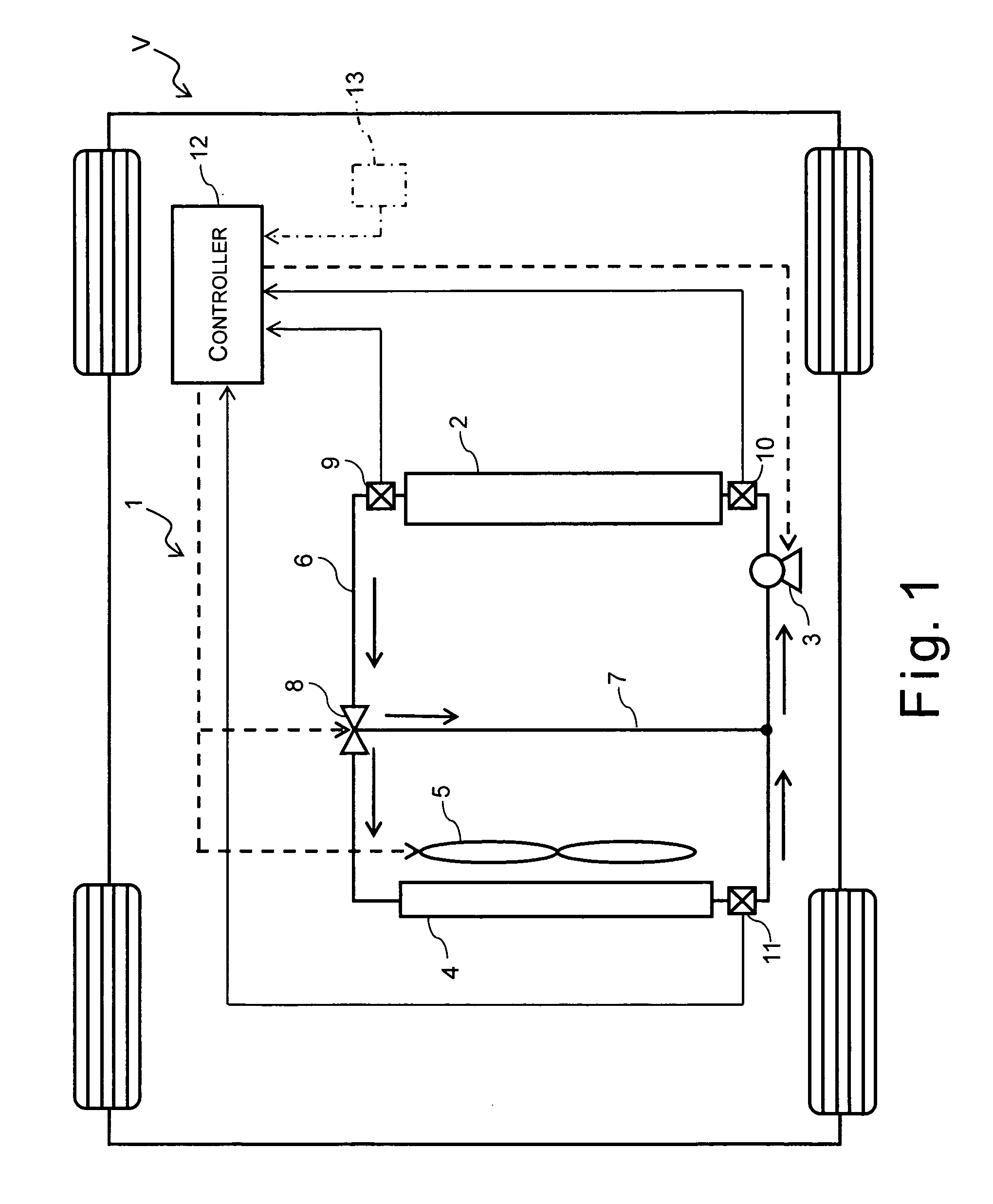
[0065] The third embodiment of the present invention is basically identical to the first embodiment explained above except for the control executed in the controller 12. Thus, the constituent components of the vehicle cooling system 1 in accordance with the third embodiment are the same as those of the first embodiment shown in FIG. 1 and detailed descriptions thereof are omitted for the sake of brevity.

[0066]FIG. 6 is a flowchart showing the computer processing executed in the controller 12 of the vehicle cooling syste...

fourth embodiment

[0076] Referring now to FIGS. 7 and 8, a fourth embodiment will now be explained. In view of the similarity between the first and fourth embodiments, the parts of the fourth embodiment that are identical to the parts of the first embodiment will be given the same reference numerals as the parts of the first embodiment. Moreover, the descriptions of the parts of the fourth embodiment that are identical to the parts of the first embodiment may be omitted for the sake of brevity.

[0077] The fourth embodiment of the present invention is basically identical to the first embodiment explained above except for the control executed in the controller 12. Thus, the constituent components of the vehicle cooling system 1 in accordance with the fourth embodiment are the same as those of the first embodiment shown in FIG. 1 and detailed descriptions thereof are omitted for the sake of brevity.

[0078]FIG. 7 is a flowchart showing the computer processing executed in the controller 12 of the vehicle ...


PUM


Abstract

A vehicle cooling system comprises a vehicle unit, a heat exchanger, a cooling fan, a coolant pump, a three-way valve, and a control unit. The heat exchanger is arranged in the coolant route to selectively receive a coolant from the coolant outlet of the vehicle unit. The cooling fan is arranged to blow cooling air to the heat exchanger. The coolant pump is arranged to circulate the coolant through the coolant route. The three-way valve is arranged to switch the coolant route between a heat exchanger route that passes through the heat exchanger and a bypass route that bypasses the heat exchanger. The control unit is configured to control operation of at least one of the cooling fan, the three-way valve and the coolant pump based on a temperature of the coolant at the heat exchanger and a temperature of the coolant at the coolant outlet of the vehicle unit.

Description

CROSS-REFERENCE TO RELATED APPLICATIONS [0001] This application claims priority under 35 U.S.C. § 119 to Japanese Patent Application No. 2005-042963. The entire disclosure of Japanese Patent Application No. 2005-042963 is hereby incorporated herein by reference. BACKGROUND OF THE INVENTION [0002] 1. Field of the Invention [0003] The present invention relates to a vehicle cooling system for removing heat generated by a vehicle unit (i.e., for cooling the vehicle unit). More particularly, the present invention relates to a vehicle cooling system configured and arranged to prevent thermal shock from occurring in a heat exchanger that is used to remove heat generated by a vehicle unit. [0004] 2. Background Information [0005] In recent years, fuel cell automobiles have been developed which operate at high efficiencies and employ larger heat exchangers than gasoline engines due to the large quantity of heat emitted. A conventional vehicle cooling system of a fuel cell automobile is config...

Claims


Application Information

Patent Timeline
IPC IPC(8): B60H1/00
CPCB60H1/00885B60H1/00892
Inventor SATO, YOUSUKEISHIKAWA, TAKAYUKIIWASAKI, MITSURU
Owner NISSAN MOTOR CO LTD
Why Eureka
Try Eureka