
High-power ultrasonic horn

a high-power, ultrasonic technology, applied in the direction of mechanical vibration separation, soldering apparatus, manufacturing tools, etc., can solve the problems of limited success in using ultrasound for large-scale chemical processes, limited frequency attainable by magnetostriction drives, and limited energy output of ultrasonic generators. achieve the effect of enhancing the penetration of ultrasonic vibrations and high vibration stress

Inactive Publication Date: 2006-09-07
SULPHCO
View PDF18 Cites 22 Cited by
  • Summary
  • Abstract
  • Description
  • Claims
  • Application Information

AI Technical Summary

Benefits of technology

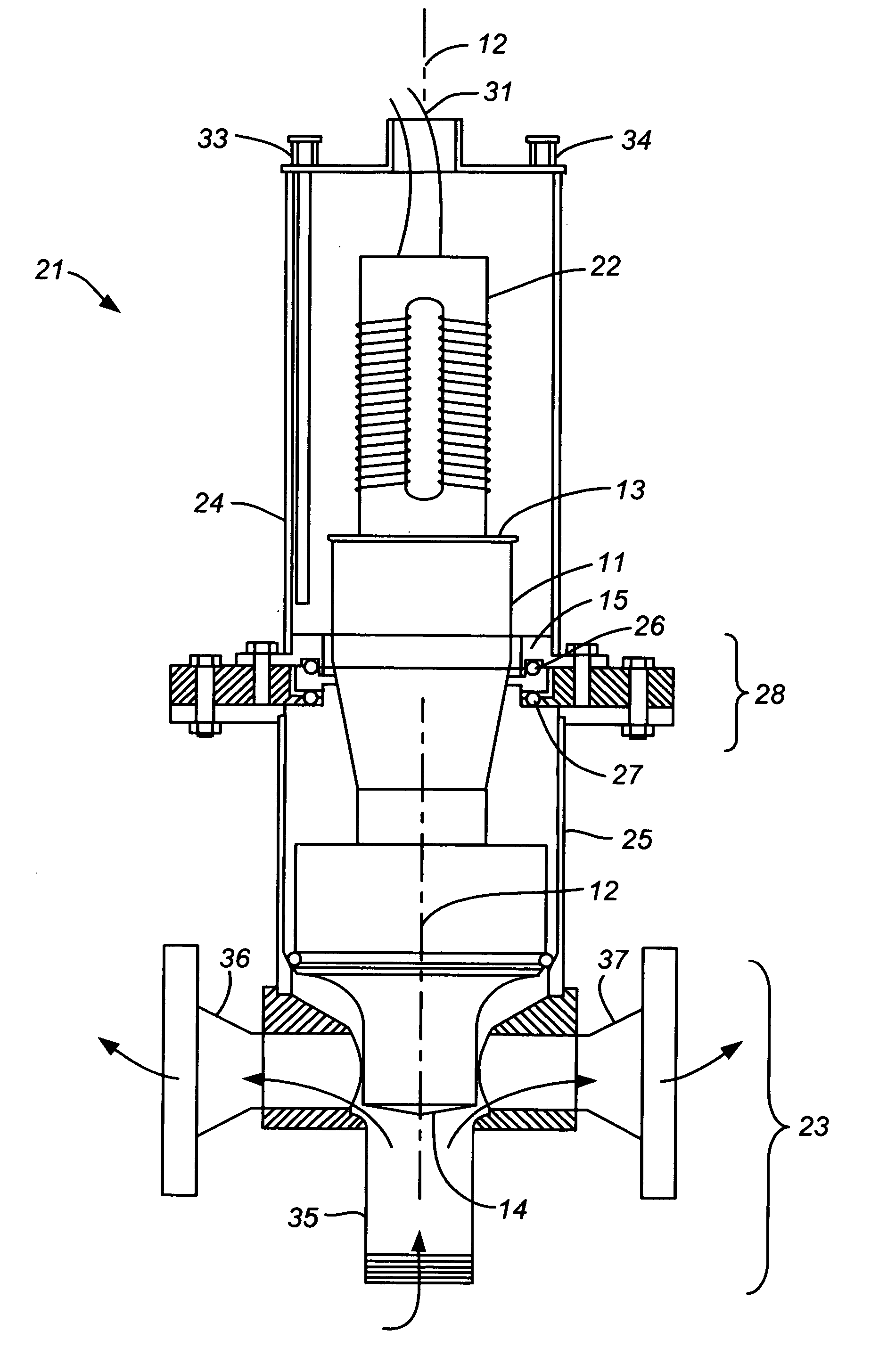
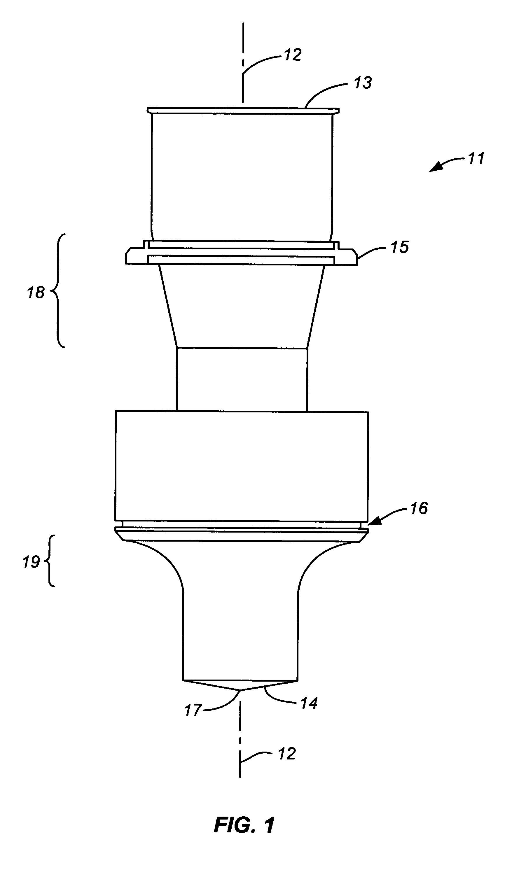
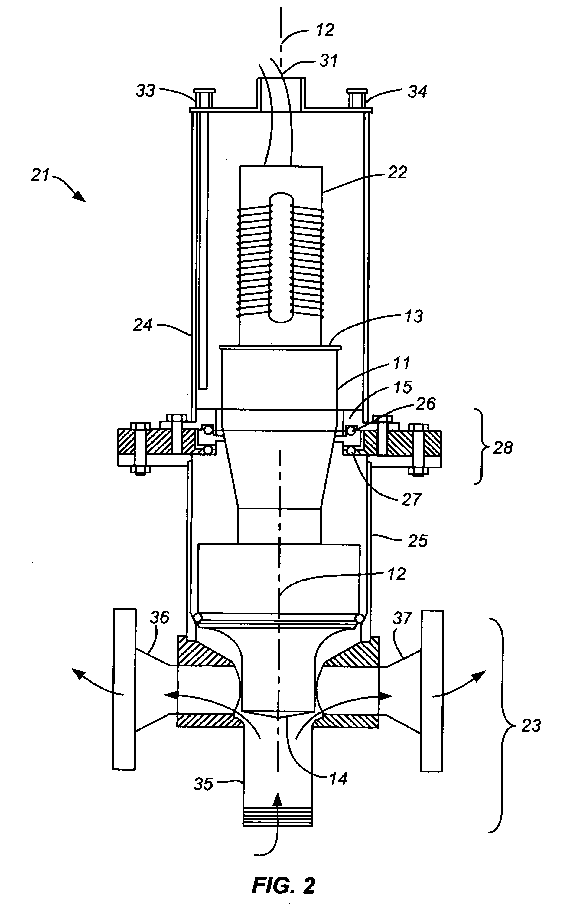
[0006] It has now been discovered that ultrasound can be supplied to a reaction system at high energy through a specially designed ultrasonic horn that can withstand the high stress of the vibrations without damage to the horn. Optimally, the horn of this invention is designed for use at a particular ultrasonic frequency, and different horns can be designed and used for different ultrasonic frequencies. The horn is a solid elongate body whose preferred length is approximately equal to a single wavelength of the ultrasonic vibrations through the horn at the selected frequency. The horn has proximal and distal ends, the proximal end adapted to be operatively joined to an ultrasonic transducer and the distal end exposed for immersion in a fluid reaction medium. The distal end is conically shaped to taper at least approximately to a point, thereby enhancing the penetration of the ultrasonic vibrations into the body of the reaction medium. A mounting fixture on the horn located between the proximal and distal ends allows the horn to be mounted to the wall of a reactor vessel with the distal end inside the vessel and the proximal end outside.

Problems solved by technology

Ultrasound generators are generally of limited energy output due to the power needed to drive the vibrations and the heat generated by ultrasonic transducers.
Because of these limitations, the use of ultrasound for large-scale chemical processes has met with limited success.
One means of achieving ultrasonic vibrations at a relatively high power is by the use of magnetostriction-driven ultrasound transducers, but frequencies attainable by magnetostriction drives are still only moderate in magnitude.
These systems are not suitable for high-throughput reactions where a high reaction yield is required.

Method used


Image

  • High-power ultrasonic horn
  • High-power ultrasonic horn
  • High-power ultrasonic horn

Examples


Embodiment Construction

[0012] As noted above, the length of the ultrasonic horn of this invention is optimally chosen with reference to the wavelength of the ultrasonic vibrations. Thus, once an ultrasonic frequency is selected, the corresponding wavelength of the vibrations in the material from which the horn is manufactured and hence the optimal longitudinal dimension of the horn can be determined. The frequencies known as ultrasonic frequencies are well known and will be readily apparent to those familiar with the use of ultrasound in any of its various applications. In general, ultrasonic vibrations have frequencies within the broad range of from about 15 kHz to about 100 kHz. For the purposes of this invention, a preferred range of ultrasonic frequencies is from about 15 kHz to about 30 kHz, and the most preferred is from about 15 kHz to about 20 kHz. Preferably, the length of the horn is such that the horn operates as a full wavelength resonator for vibrations in the ultrasonic range traveling longi...


PUM

PropertyMeasurementUnit
Lengthaaaaaaaaaa
Lengthaaaaaaaaaa
Fractionaaaaaaaaaa

Abstract

An ultrasonic horn for use in a chemical reactor is formed as a unitary piece of material whose length is approximately equal to the wavelength of ultrasonic waves through the material at a selected ultrasonic frequency. The horn has a conically shaped distal end and a mounting surface at its proximal end, plus a mounting fixture between the proximal and distal ends for mounting the horn to a flow-through reactor with the distal end protruding into the reactor interior while the proximal end extends outside the reactor. The horn further contains a seal between the proximal and distal ends to seal the horn to the interior of a reaction vessel in a fluid-tight manner. With the unitary construction and the conical distal end, the horn is capable of transmitting high power ultrasonic waves to the reactor interior without damage to the horn or its mounting fixtures.

Description

BACKGROUND OF THE INVENTION [0001] 1. Field of the Invention [0002] This invention resides in the field of process equipment used in the treatment of materials in liquid media by ultrasound. [0003] 2. Description of the Prior Art [0004] The use of ultrasound for driving chemical reactions is well known. Examples of publications that describe chemical uses of ultrasound are Suslick, K. S., Science, vol. 247, p. 1439 (1990), and Mason, T. J., Practical Sonochemistry, A User's Guide to Applications in Chemistry and Chemical Engineering, Ellis Norwood Publishers, West Sussex, England (1991). Of the various sonicating systems that have been developed, those known as “probe”-type systems include an ultrasonic transducer that generates ultrasonic energy and transmits that energy to an ultrasonic horn for amplification. [0005] Ultrasound generators are generally of limited energy output due to the power needed to drive the vibrations and the heat generated by ultrasonic transducers. Because...

Claims


Application Information

Patent Timeline
IPC IPC(8): B23K20/10
CPCB01J19/10B06B3/00B23K20/10
Inventor GUNNERMAN, RUDOLF W.
Owner SULPHCO
Learn More