Phosphor mixture and light emitting device

a technology of phosphor mixture and light emitting device, which is applied in the direction of discharge tube luminescent screen, discharge tube/lamp details, luminescent composition, etc., can solve the problems of reducing emission efficiency, affecting the effect of emission efficiency, etc., to achieve excellent color rendering properties, and small color shift

Active Publication Date: 2006-09-07
NICHIA CORP +1
View PDF47 Cites 87 Cited by
  • Summary
  • Abstract
  • Description
  • Claims
  • Application Information

AI Technical Summary

Benefits of technology

[0036] In the phosphor mixture according to any one of the second aspect to twelfth aspect, little variation is shown in the peak value of the relative emission intensity under influence of the change in surrounding temperature. Therefore, when the phosphor mixture is irradiated with a predetermined excitation light, the emitted light from the phosphor mixture is synthesized with the excitation light, and the light

Problems solved by technology

However, the emission efficiency is extremely decreased, thereby also decreasing in emission intensity at the temperature of not less than 100° C. The

Method used


Image

  • Phosphor mixture and light emitting device
  • Phosphor mixture and light emitting device
  • Phosphor mixture and light emitting device

Examples


example 1

1) Manufacture of the Phosphor and Temperature Characteristic Evaluation of the Phosphor

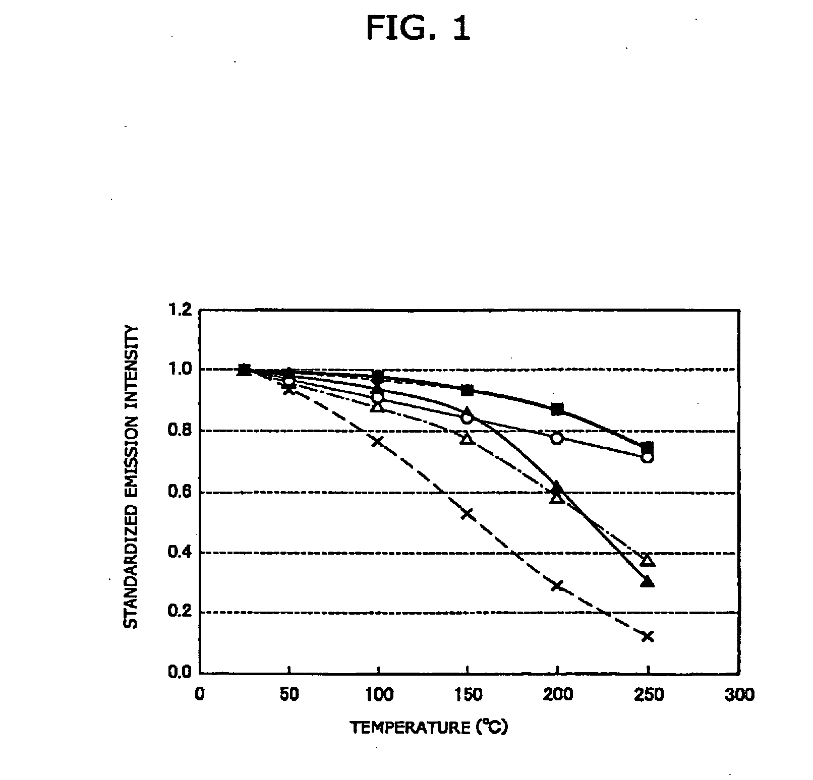
[0095] By the method explained in the examples, each raw material was weighed, with the mixing ratio set to be 0.980 / 3 mol of Ca3N2, 1 mol of AlN, 1 / 3 mol of Si3N4, and 0.020 / 2 mol of Eu2O3, and mixed in a glove-box filled with nitrogen gas. Then, the raw materials thus mixed was fired for 3 hours at 1600° C. in a nitrogen atmosphere of 0.05 MPa, and the red phosphor CaAlSiN3:Eu (sample 1) of the present invention was thus manufactured. The emission intensity at 25° C. under the excitation of the light with 467 nm wavelength was measured, and the emission intensity thus obtained was defined as P25. Next, the light emission intensity at T° C. under the excitation of the light with the same 467 nm wavelength was measured, and the emission intensity thus obtained was defined as PT. The temperature characteristic of the variation in the emission intensity (100×(P25−PT) / P25 was shown in table 1. Fur...

example 2

1) Adjusting Method of the Phosphor Mixture

[0129] Explanation is given to the manufacturing method of the phosphor mixture using the red phosphor CaAlSiN3:Eu (sample 1) and the phosphor Ca3Sc2Si3O12:Ce (sample 3) having the emission spectrum with a maximum peak in the wavelength range from 500 nm to 630 nm and having a garnet crystal structure with Ce as an activator.

[0130] The emission spectra of the phosphor CaAlSiN3:Eu (sample 1) and the phosphor Ca3Sc2Si3O12:Ce (sample 3) under the excitation of the excitation light of 467 nm wavelength were respectively measured, and further, the emission spectrum (an emission spectrum of the light emitting part) of the excitation light was measured. From such two kinds of emission spectra, the relative mixing ratio of each phosphor was obtained by simulation, so that the correlated color temperature obtained by synthesizing the light emitted from the phosphor mixture and the excitation light was 4500K. Based on the result of this simulation...


PUM

PropertyMeasurementUnit
Temperatureaaaaaaaaaa

Abstract

To provide a phosphor mixture realizing a light emitting device having a phosphor and a light emission element, by which light emission is performed, with a small color shift due to a feeding current and having an excellent color rendering properties. CaAlSin3:Eu as a red phosphor and YAG:Ce as a yellow phosphor are manufactured, and emission spectra thereof are obtained. Meanwhile, the emission spectrum of an excitation light emitted by a light emitting part is obtained. From the emission spectra thus obtained, a relative mixing ratio of each phosphor is obtained by simulation, so that a correlated color temperature of the light emitting device becomes a target temperature. Then, based on the relative mixing ratio thus obtained, each phosphor is measured and mixed, and a phosphor mixture is thereby obtained.

Description

BACKGROUND OF THE INVENTION [0001] 1. Field of the Invention [0002] The present invention relates to a phosphor mixture used for an illumination device such as a light emitting diode (LED), a fluorescent display tube, and a fluorescent lamp, and a light emitting device using the phosphor mixture. [0003] 2. Description of the Related Art [0004] As a light emitting device conventionally used as an illumination device, a discharge-type fluorescent lamp and an incandescent lamp and so forth are given as examples. However, in recent years, a white LED lighting unit using a light emitting diode (referred to as LED in some cases hereafter) that emits white light has been developed. Compared with the conventional light source for illumination, the white LED lighting unit serves as an ideal illumination device having advantages that the heat generation is reduced, an emission efficiency is excellent, power consumption is reduced, composed of only LED element or LED element and a phosphor, ha...

Claims


Application Information

Patent Timeline
IPC IPC(8): H01J1/62H01J63/04H01L33/50H01L33/56H01L33/60H01L33/62
CPCC04B35/581C04B35/584C04B2235/3224C04B2235/3852C04B2235/3865C04B2235/3873C09K11/0883C09K11/7734H01L33/502H01L33/504H01L2224/48091H01L2224/48247H01L2224/48257H01L2924/00014C09K11/77348
Inventor NAGATOMI, AKIRAGOTOH, MASAHIROSAKANE, KENJI
Owner NICHIA CORP
Why Eureka
Try Eureka