Imaging system
a technology of image and optical material, applied in the field of image system, can solve the problems of insufficient color correction, insufficient transparency of purely refractive system, and difficulty in providing purely refractive system, and achieve the effect of small amount of transparent optical material, and high image side numerical apertur
- Summary
- Abstract
- Description
- Claims
- Application Information
AI Technical Summary
Benefits of technology
Problems solved by technology
Method used
Image
Examples
embodiment 600
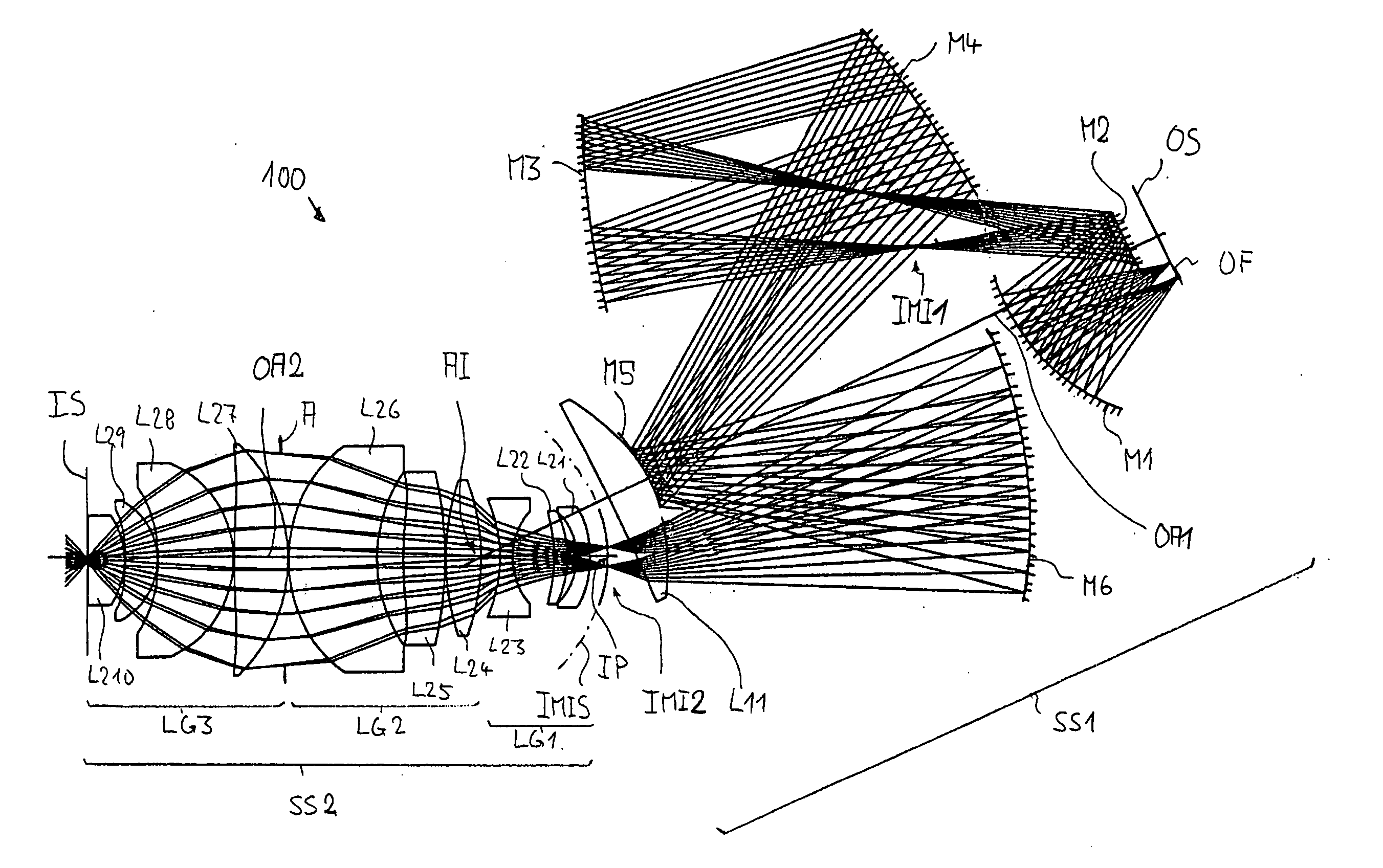
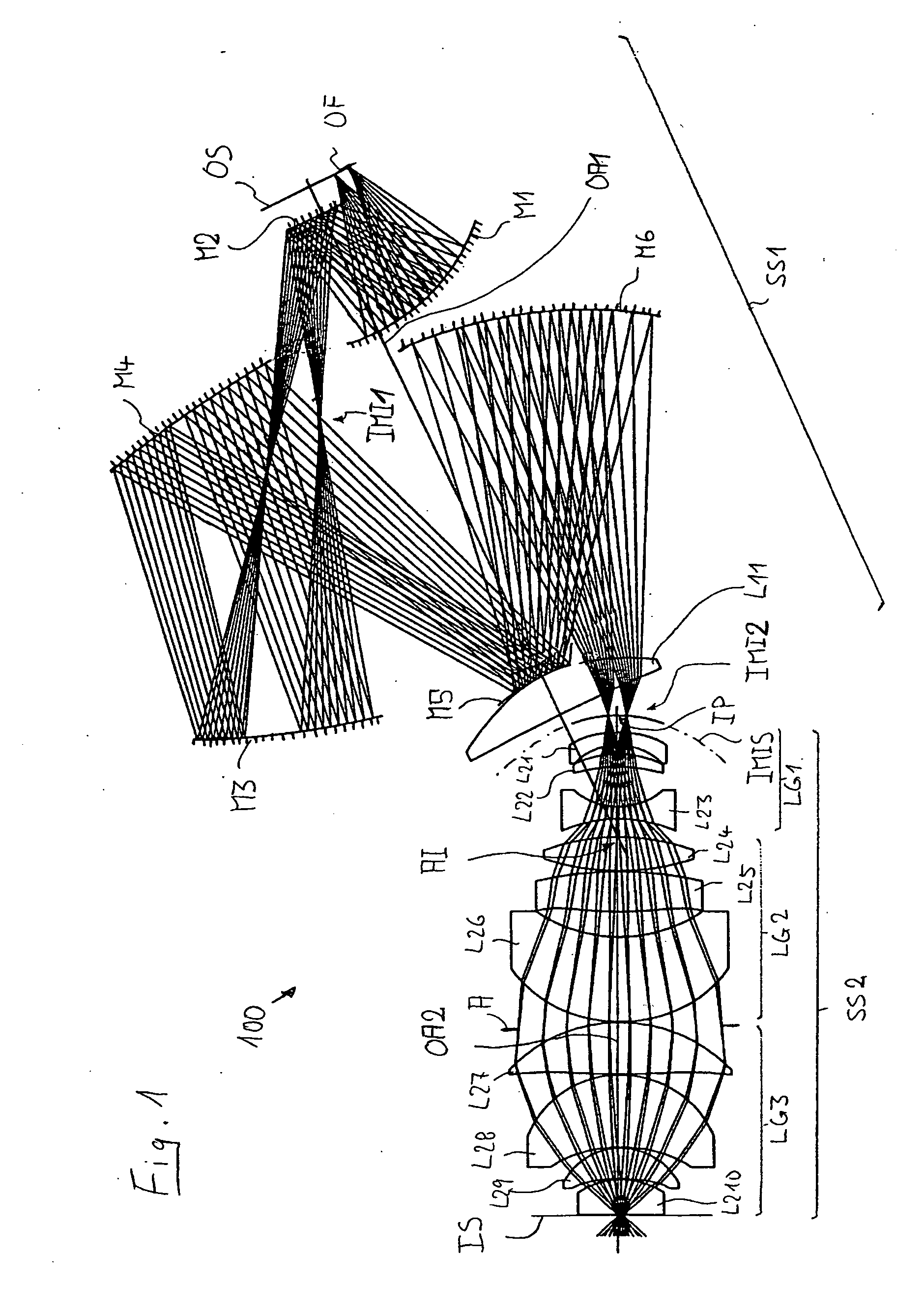
[0098] Another embodiment 600 is presented in FIG. 6. Using a similar structure as the aforementioned embodiment, the two subsystems SS1 and SS2 are sharing a common optical axis and are forming an intermediate image IMI2 strongly affected by overcorrected Petzval field curvature. With this overcorrection the undercorrection of the third subsystem SS3 is compensated.
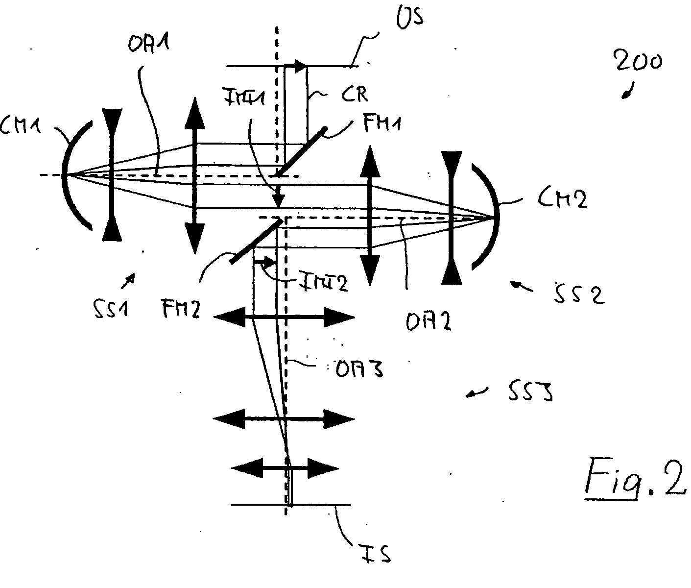
[0099] Making the field for the third subsystem SS3 to be an axial field implies that the optical axis OA3 of the third subsystem must be tilted to the folded optical axis OA2 of the second subsystem SS2. Using the first folding mirror FM1 with a mplanar mirror surface inclined at a small angle (e.g. <30°) to the mirror surface of the second folding mirror one can adjust the tilt angle of this mirror in order to make the final image surface being parallel to the object surface. This also applies to the system in FIG. 3.
embodiment 700
[0100] In a further embodiment 700 exemplarily shown in FIG. 7 the beam folding situation at the folding mirrors FM1 and FM2 can further be relaxed with respect to the embodiments of FIG. 2 to 6. The further relaxation is obtained by a refractive relay system RS which is inserted between the object surface OS and the field surface immediately upstream of the first folding mirror FM1. This field surface forms the object surface in FIGS. 2 to 6, whereas in the embodiments according to FIGS. 7 to 18 the field surface immediately upstream of the first folding mirror FM1 is an intermediate image IMI0 formed by a refractive relay system RS from the object field OF.
[0101] The projection objective 700 in FIG. 7 is a variant of the projection objective of FIG. 2 where all optical elements downstream of the intermediate image IMI0 formed by the relay system RS are identical to those of FIG. 2. Therefore, reference is made to that description. Whereas a certain axial distance between the objec...
embodiment 800
[0102] The embodiment 800 of FIG. 8 is a variant of the projection objective 700 of FIG. 7. The main difference is that the relay system RS forms a flat intermediate image IMI0. As a consequence the object field for the first subsystem can be configured as an axial field, thereby significantly reducing the etendue of the first subsystem. This type of relay-system RS can also be implemented in the objectives presented as preferred embodiments 900 to 1200.
PUM
 Abstract
Description
Claims
Application Information
 - R&D
- Intellectual Property
- Life Sciences
- Materials
- Tech Scout
- Unparalleled Data Quality
- Higher Quality Content
- 60% Fewer Hallucinations
Browse by: Latest US Patents, China's latest patents, Technical Efficacy Thesaurus, Application Domain, Technology Topic, Popular Technical Reports.
© 2025 PatSnap. All rights reserved.Legal|Privacy policy|Modern Slavery Act Transparency Statement|Sitemap|About US| Contact US: help@patsnap.com


