Image forming device

a technology of forming device and image, which is applied in the direction of instruments, electrographic process equipment, optics, etc., can solve problems such as image defects, and achieve the effect of eliminating static electricity

Active Publication Date: 2006-09-07
KYOCERA DOCUMENT SOLUTIONS INC
View PDF7 Cites 13 Cited by
  • Summary
  • Abstract
  • Description
  • Claims
  • Application Information

AI Technical Summary

Benefits of technology

[0015] The image forming device according to a first aspect of the present invention is comprising an image supporter, supply unit, transferring means, and separating means. The image supporter supports a toner image and rotates. The supply unit supplies a sheet like recording medium to the image supporter. The transferring means transfers the toner image onto the sheet like recording medium transported by the supply unit. The separating means is located downstream from the transferring means in the recording medium transport direction, has a plurality of separation needles located along the direction orthogonal to the recording medium transport direction, and eliminates static electricity from the recording medium by applying a separation voltage to the separation needles in order to separate the recording medium from the image supporter. Furthermore, the separating means is established downstream from the separation needles in the recording medium transport direction, and include a transport unit which transports the recording medium. The transport unit is positioned in a direction orthogonal to the recording medium transport direction, has a plurality of transport plates which guide the transport of the recording medium and a conductive member positioned between the plurality of transport plates, and the conductive member is grounded and visible without interference from the tip end of the separation needles.

Problems solved by technology

Furthermore, if the separation voltage is increased in order to prevent poor separation of the recording medium, there is a possibility that dielectric breakdown to the photosensitive drum will occur if an amorphous silicon (A-Si) photosensitive drum is used, thus causing image defects.

Method used


Image

  • Image forming device
  • Image forming device
  • Image forming device

Examples


Embodiment Construction

[0031] Embodiments of the present invention will be described below with reference to the figures.

[0032] Structure of Image Forming Device

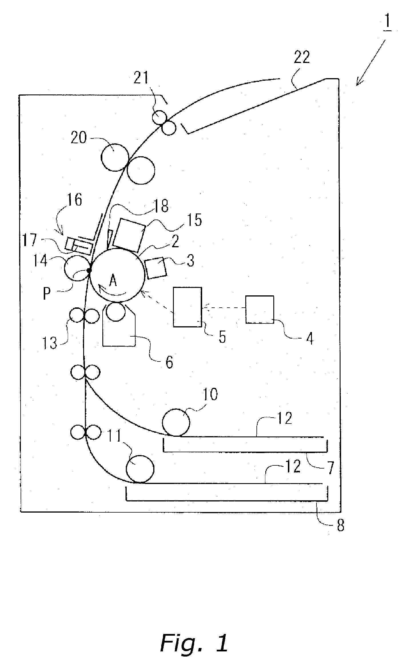
[0033]FIG. 1 shows the schematic construction of an image forming device according to the present embodiment. In FIG. 1, the photosensitive drum (image supporter) 2 rotates in the direction of arrow A in the figure, and the surface is uniformly charged by the charging means. In this condition, laser light is irradiated onto the surface of the photosensitive drum by an exposing means 5 which moves based on a control signal from a controlling means 4, and a static electric latent image is formed on the surface thereof. Next, toner is supplied as a developing agent by a developing means 6 onto the surface of the photosensitive drum 2, and the static electric latent image becomes visible as a toner image.

[0034] On the other hand, a sheet like recording medium 12 (such as copy paper, plastic film, or the like, hereinafter simply referred to as the s...


PUM


Abstract

A plurality of separation needles are arranged downstream from a transfer roller in the sheet transport direction along a direction which is orthogonal to the sheet transport direction, and when a separation voltage is applied to the separation needles, an electrical discharge occurs between the photosensitive drum and the separation needles, and a sheet which has been charged by the transfer roller has static charge eliminated and is separated from the photosensitive drum. Furthermore, a transport unit established downstream from the separation needles in the sheet transport direction has a plurality of transport plates which guide the transport of the sheet, and a grounding plate which is located between these transport plates, and the grounding plate is connected to the grounding unit of the device body such that the grounding plate can be seen without interference from the tip end of the separation needles.

Description

BACKGROUND OF THE INVENTION [0001] 1. Field of the Invention [0002] The present invention relates to an image forming device such as a copier, printer, or fax machine, and in further detail relates to an image forming device which can easily eliminate static electricity and separate a sheet like recording medium, onto which a toner image has been transferred, from an image supporter. [0003] 2. Background Information [0004] Generally, in image forming devices such as electrophotographic copiers, printers, and fax machines, a toner image is formed or transferred to an image supporter such as a photosensitive drum or an intermediate transfer medium, and then the toner image which has been formed or transferred to the surface of the image supporter is transferred to a sheet like recording medium (such as copy paper or a plastic film). Next, this recording medium is separated from the surface of the image supporter by separating means, and then the recording medium which has been separat...

Claims


Application Information

Patent Timeline
Patent Type & Authority Applications(United States)
IPC IPC(8): G03G15/14
CPCG03G15/6532
Inventor TSUJITA, MITSUJI
Owner KYOCERA DOCUMENT SOLUTIONS INC
Why Eureka
Try Eureka