Multi functional pump for pumping molten metal
a multi-functional, pump technology, applied in the direction of machines/engines, mechanical equipment, liquid fuel engines, etc., can solve the problems of compromising the physical properties of metal articles, requiring a large amount of fuel by burners, and undesirable hydrogen gas in metals, etc., to achieve the effect of convenient pumping
- Summary
- Abstract
- Description
- Claims
- Application Information
AI Technical Summary
Benefits of technology
Problems solved by technology
Method used
Image
Examples
first embodiment
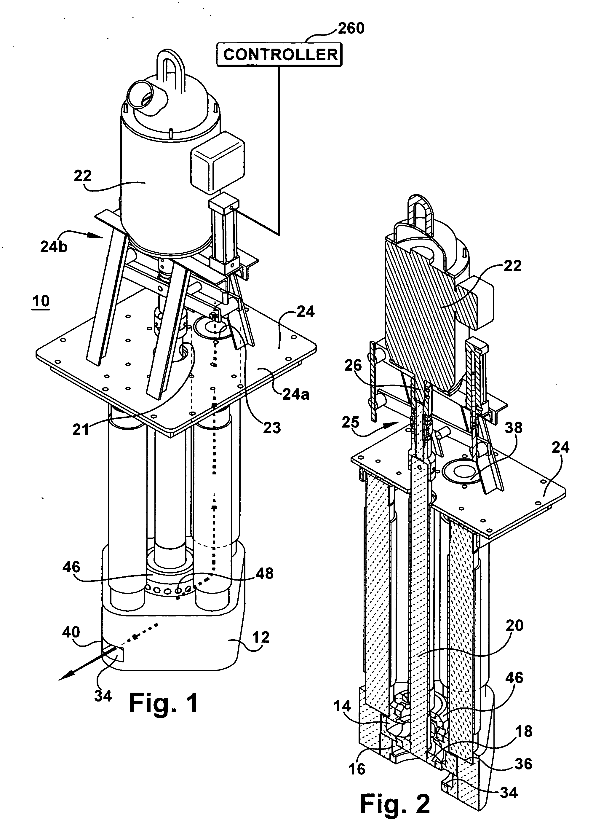
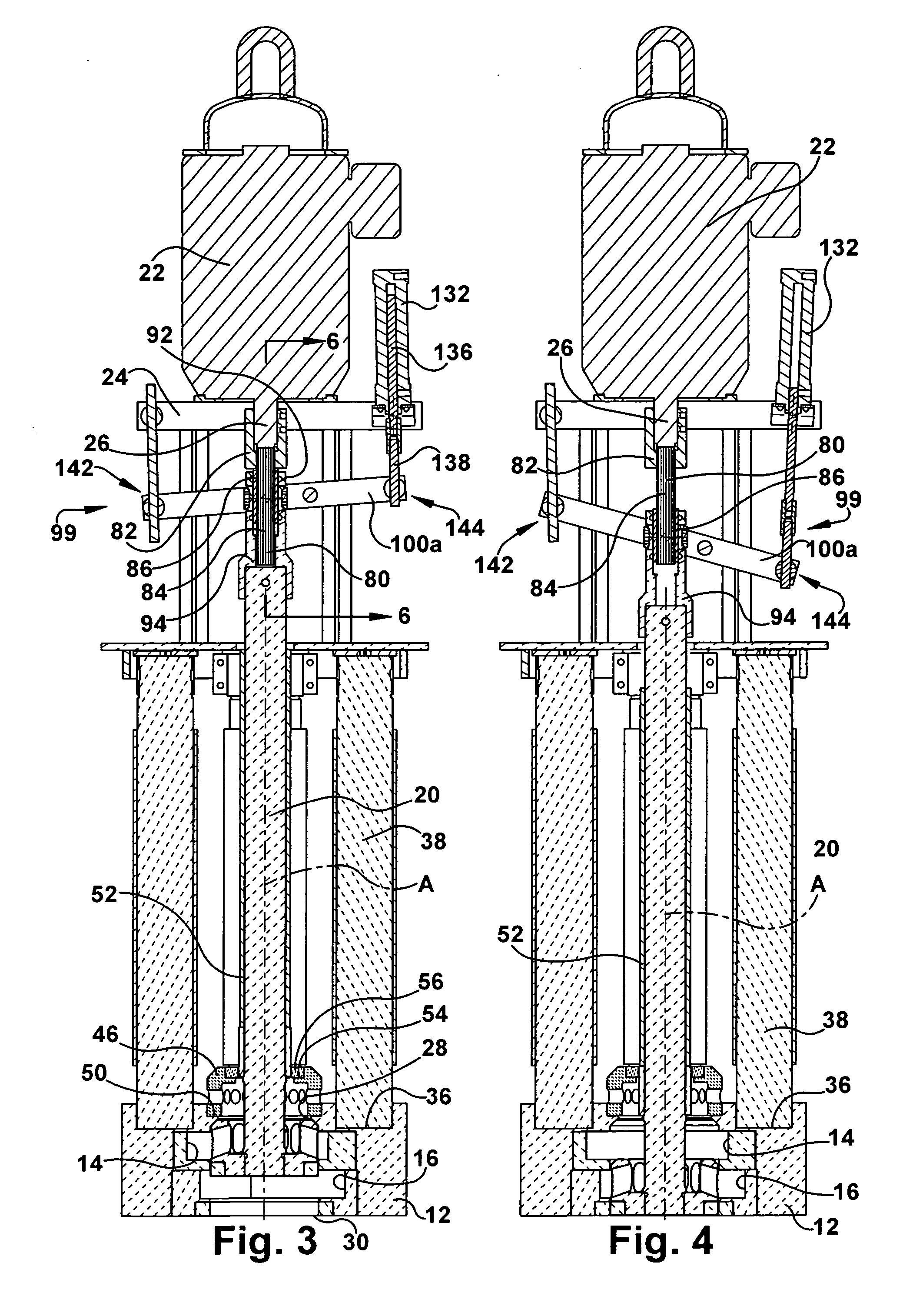
[0044] Referring now to the drawings, the present invention features a pump 10 including a base 12 adapted to be submerged in molten metal and including an upper transfer impeller chamber 14 stacked or disposed over a lower circulation impeller chamber 16. An impeller 18 is connected to a lower end portion of a pump shaft 20. A motor 22 is supported above the molten metal on a motor mount 24. The motor mount 24 can have various configurations and in this particular design includes a base plate 24a having an opening 21 for accommodating the shaft and may include an opening 23 for accommodating a riser. The motor mount also includes brackets 24b for supporting the motor 22 above the base plate 24a. The upper end portion of the shaft is coupled by coupling 25 to the drive shaft 26 of the motor, which rotates the impeller in a selected impeller chamber. The base includes upper and lower circular openings 28, 30 that are concentric to each other around the axis of rotation A of the impel...
second embodiment
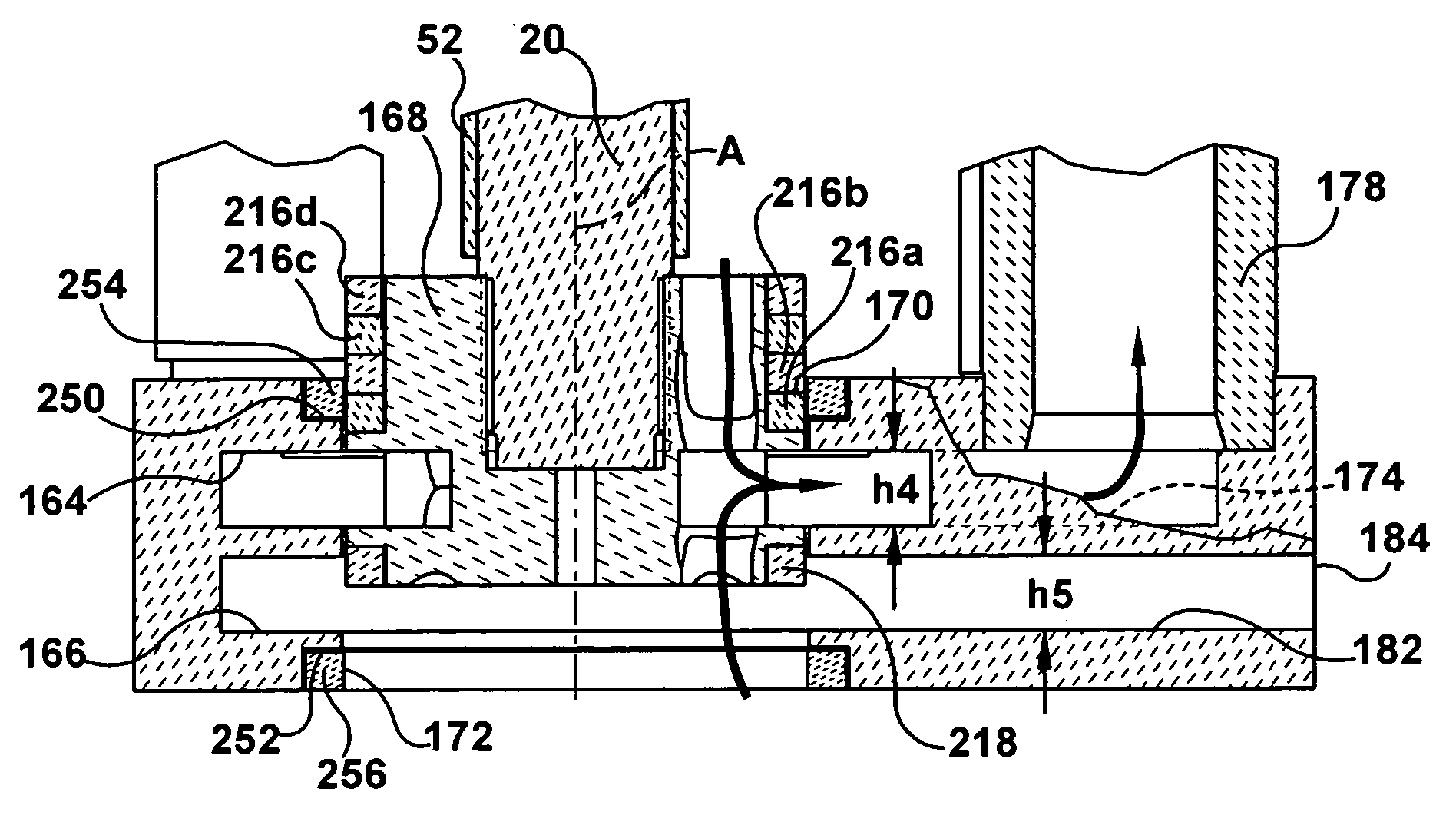
[0058] Referring now to FIGS. 11-18 of the drawings, the present invention features a pump 160 in which the impeller can be moved to straddle positions between impeller chambers. The pump comprises a base 162 including an upper transfer impeller chamber 164 and a lower circulation impeller chamber 166. Like reference numerals represent like parts throughout the several views of this disclosure and thus, the same components from the pump in FIGS. 1-10 need not be discussed again here. The impeller positioning device 99 described in FIGS. 1-10 is also used in the pumps shown in FIGS. 11-21 but is omitted to improve the clarity of the drawings. An impeller 168 is connected to a lower end portion of the pump shaft 20. Rotation of the drive shaft rotates the pump shaft and thus rotates the impeller in the impeller chambers.
[0059] In this exemplary design the base includes concentric upper and lower circular openings 170, 172 (FIG. 13) which can function as inlet openings and through whic...
third embodiment
[0081] the present invention features a pump 270 including a base 272 having three impeller chambers. The impeller chambers in this pump can be any combination and arrangement of transfer and circulation impeller chambers. In one exemplary design shown in FIGS. 19-21, the base includes an upper transfer impeller chamber 274, a middle circulation impeller chamber 276, and a lower transfer impeller chamber 278. The base includes an upper transfer discharge passageway 280 extending from the upper transfer impeller chamber to a first transfer location, a middle circulation discharge passageway 282 extending from the middle circulation impeller chamber to a discharge opening 283 in the exterior surface of the base and a lower discharge passageway 284 extending from the lower transfer impeller chamber to a second transfer location.
[0082] A socket 286 is disposed in the base in fluid communication with the upper discharge passageway 280. A lower portion of a first outlet conduit 288 is cem...
PUM
| Property | Measurement | Unit |
|---|---|---|
| Flow rate | aaaaa | aaaaa |
| Electrical resistance | aaaaa | aaaaa |
Abstract
Description
Claims
Application Information
 - R&D
- Intellectual Property
- Life Sciences
- Materials
- Tech Scout
- Unparalleled Data Quality
- Higher Quality Content
- 60% Fewer Hallucinations
Browse by: Latest US Patents, China's latest patents, Technical Efficacy Thesaurus, Application Domain, Technology Topic, Popular Technical Reports.
© 2025 PatSnap. All rights reserved.Legal|Privacy policy|Modern Slavery Act Transparency Statement|Sitemap|About US| Contact US: help@patsnap.com


