Non-articulated rotor and rotorcraft comprising a rotor of this type

a non-articulation rotor and rotorcraft technology, which is applied in the direction of marine propulsion, liquid fuel engines, and vessel construction, etc., can solve the problems of reducing the service life reducing the durability and mechanical properties of the rotor blade, and reducing the flapping hinge distance or reducing it below a specific value. , to achieve the effect of small fictitious or virtual flapping hinge distance, improved aerodynamic and mechanical properties, and improved mechanical properties

Active Publication Date: 2006-09-07
AIRBUS HELICOPTERS DEUT GMBH
View PDF5 Cites 5 Cited by
  • Summary
  • Abstract
  • Description
  • Claims
  • Application Information

AI Technical Summary

Benefits of technology

[0014] The hingeless rotor according to the present invention possesses improved aerodynamic and mechanical properties as well as a very small fictitious or virtual flapping hinge distance. By means of the blade connector loop of the rotor according to the present invention, identical rotor-blade connectors can be made available even for a multi-blade rotor. By way of the blade connector loop, a respective rotor blade can be mounted on the rotor head in very flexurally soft fashion and with a greater connection softness, and with a small fictitious flapping hinge distance, i.e. one considerably decreased as compared with conventional hingeless rotors.
[0015] Because the blade connector loop as a rule possesses no direct attachment to the rotor mast, i.e. is free to move with respect to the rotor mast, and can be embodied in physically very flat and aerodynamically favorable fashion, the loop can elastically deflect in the flapwise direction as far as the rotor axis (or even beyond the rotor axis) almost without hindrance. The fictitious flapping hinge distance resulting therefrom can therefore be as little as 0%. Without discrete components and simply by way of the elasticity or bendability of the blade connector loop and / or the adjacent rotor-blade regions, it is thereby possible to implement, for example, a so-called gimbal rotor. A rotor having a small flapping hinge distance is perceived by passengers of a rotorcraft to be pleasant in terms of its flying characteristics. The embodiment according to the present invention moreover allows a reduction in the vibrations occurring at the rotor, and an improvement in flying characteristics and flying properties.
[0016] The blade connector loop or its blade foot region can moreover constitute a fictitious flapping hinge, and furthermore can be configured if necessary in highly torsionally soft fashion, so that bearingless blade angle adjustment can easily be implemented. The blade connector loop, or subregions thereof, can thus additionally assume the function of a very short and compact torsion element for blade angle adjustment. At least subregions of the blade connector loop and / or adjacent rotor-blade regions can be enclosed by a so-called control bag.
[0017] In addition, the partial length of the available rotor disc radius necessary for creation of the virtual flapping hinge is very small as compared with conventional hingeless or bearingless rotors. The parts of the rotor disc radius thus saved are therefore available for aerodynamically effective profiled regions of a rotor blade. Air resistance is thus reduced, and lift increased. In combination with the construction of the rotor-blade connector loop, which can per se be made very thin and flat, the aerodynamic quality of the rotor is therefore improved. The rotor according to the present invention can in principle be configured with both a high and a low lead-lag stiffness, the flapwise stiffness and lead-lag stiffness being presettable in design terms practically independently of one another. The wide loop shape of the blade connector and the loop foot region, as well as further structural features possible in this connection that are explained in detail below, nevertheless make possible, in particular, easy embodiment of a lead-lag-stiff attachment of the rotor blades to the rotor head.
[0018] In combination with the small flapping hinge distance (as low as 0%) that is achievable, this is very advantageous for specific applications, for example in a tilting rotor for a tiltrotor helicopter or tiltrotor aircraft. The reason is that the lead-lag deformations, resulting from Coriolis forces, which otherwise occur upon tilting of the tilting rotor in combination with a flapwise motion, can hereby be eliminated. A design that is advantageously adapted to the stresses that occur, and high rotor strength simultaneously with low weight, are therefore achievable. With a rotor having a lead-lag-stiff design as well as a large flapping hinge distance and consequently an undiminished Coriolis force, on the other hand, it may in some circumstances become impossible to guarantee sufficient stability for the tilting rotor.
[0019] It is furthermore possible, with the aid of the loop principle according to the present invention, to keep the rotor mast, as well as any applicable further add-on elements of the blade connector loop, free of centrifugal force, i.e. unstressed by the very large centrifugal forces acting on the rotor blades during continuous rotor operation. This is described below in further detail. This advantageous effect is very easy to achieve, particularly with multi-blade rotors. Depending on the configuration of the rotor, the centrifugal forces of respectively oppositely located rotor blades can in fact be mutually canceled out. The centrifugal force is transferred in this context, very favorably, over the relative large loop diameter, which corresponds at least to the diameter of the rotor mast but as a rule should be larger.

Problems solved by technology

This relative high natural flapping frequency, and the vibrations that result therefrom in the case of a bearingless rotor, are disadvantageous in terms of the helicopter's flying characteristics, and lead to large stresses on the blade connector and blade neck.
Because of the large stresses on the rotor blade and blade connector in a bearingless rotor, and the strength of those components that must be ensured in that context, it is extremely difficult to reduce the flapping hinge distance or decrease it below a specific value.
In conventional bearingless rotors, a small flapping hinge distance would considerably reduce the durability and service life of the rotor blade in question, which is disadvantageous or even hazardous.
A large flapping hinge distance can also be disadvantageous from an aerodynamic standpoint, since the total air resistance of the rotor elements extending from the rotor axis to the fictitious flapping hinge, in particular that of the aforesaid structural element, is quite high; and in addition, this region, which accounts for a relatively large proportion of the rotor radius, cannot be used for an aerodynamically effective region of the rotor blade.
The disadvantages explained previously exist with this design as well.
The soft suspension of the tilting rotors on the wing of a tiltrotor helicopter, however, in contrast to a stiff cell of a conventional helicopter, causes undesired couplings between the natural wing frequency and the lead-lag frequency if the design falls below the excitation frequency.
Conventional hingeless rotors are therefore not suitable for tiltrotor applications, and would result in strength and safety problems.

Method used


Image

  • Non-articulated rotor and rotorcraft comprising a rotor of this type
  • Non-articulated rotor and rotorcraft comprising a rotor of this type
  • Non-articulated rotor and rotorcraft comprising a rotor of this type

Examples


first embodiment

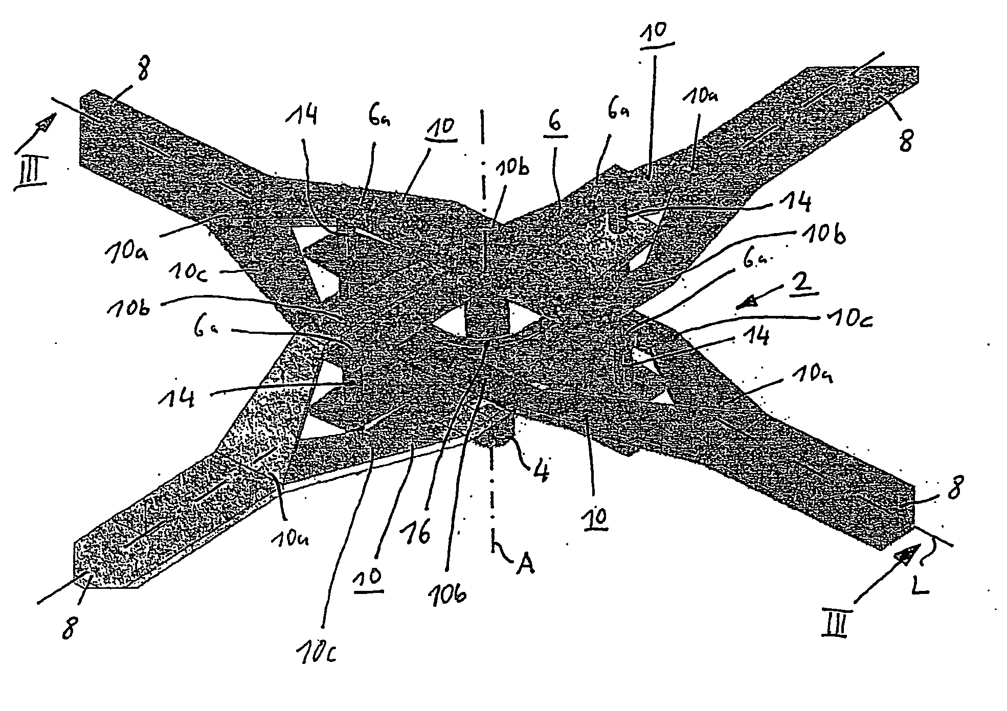
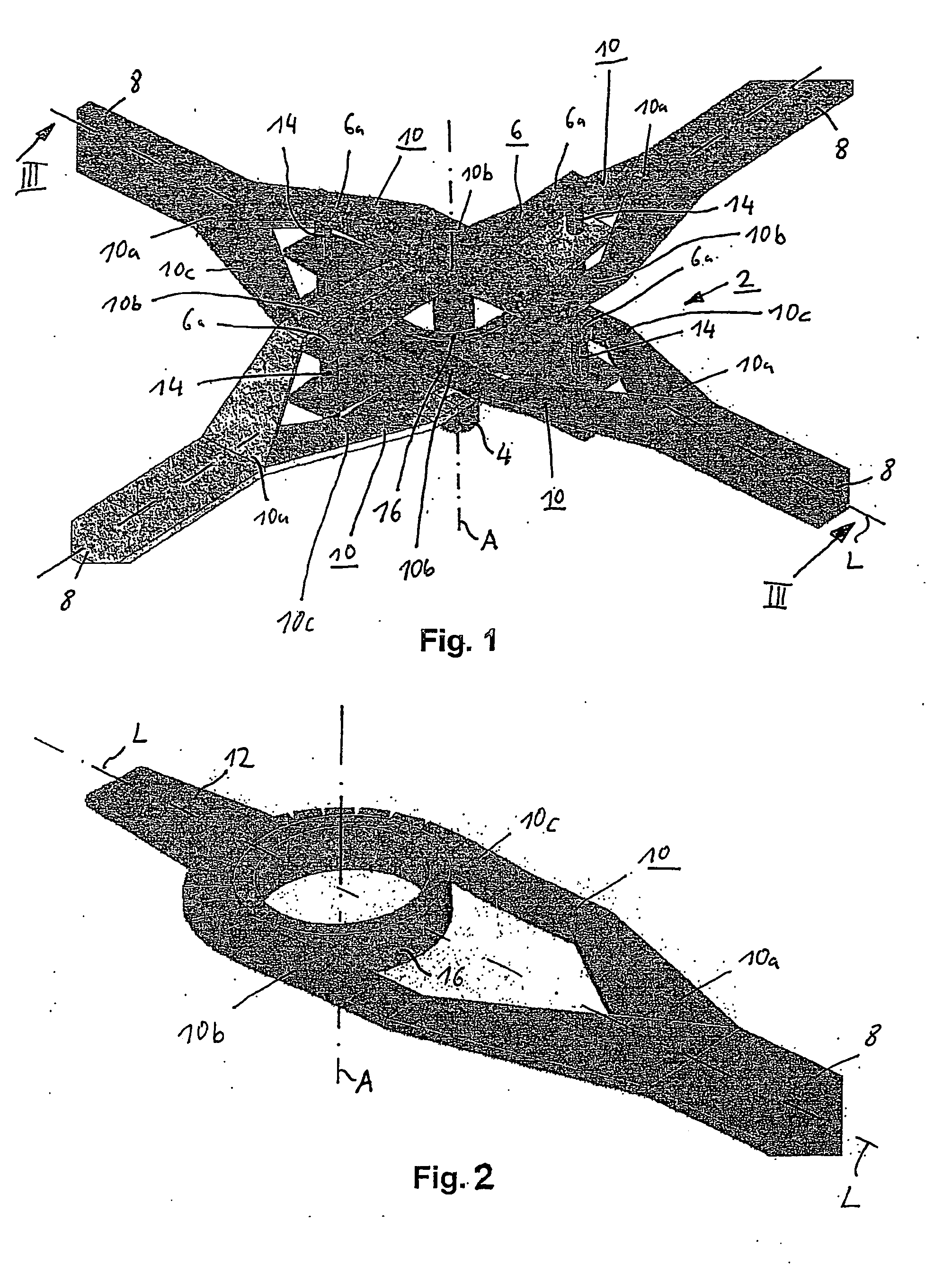
[0029]FIG. 1 is a schematic, greatly simplified perspective depiction of a hingeless rotor according to the present invention, in accordance with a FIG. 2 is a schematic, greatly simplified perspective depiction of an individual rotor-blade attachment of the rotor of FIG. 1. The hingeless rotor according to the present invention, which is here configured simultaneously as a bearingless rotor, encompasses a rotor head 2, a rotor mast 4 having a rotor axis A, and a torque-transmission element 6 nonrotatably joined to rotor mast 4, that element being configured in this example as a cross-shaped rotor-head star 6 having four arms 6a. The rotor is further equipped with four similar rotor blades 8, each of which has a respective arm 6a associated with it.

[0030] For each rotor blade 8, the rotor encompasses a rotor-head-side rotor-blade connector having a centrifugal-force-discharging blade connector loop 10 which encircles rotor mast 4 in unattached fashion and is nonrotatably joined to ...

second embodiment

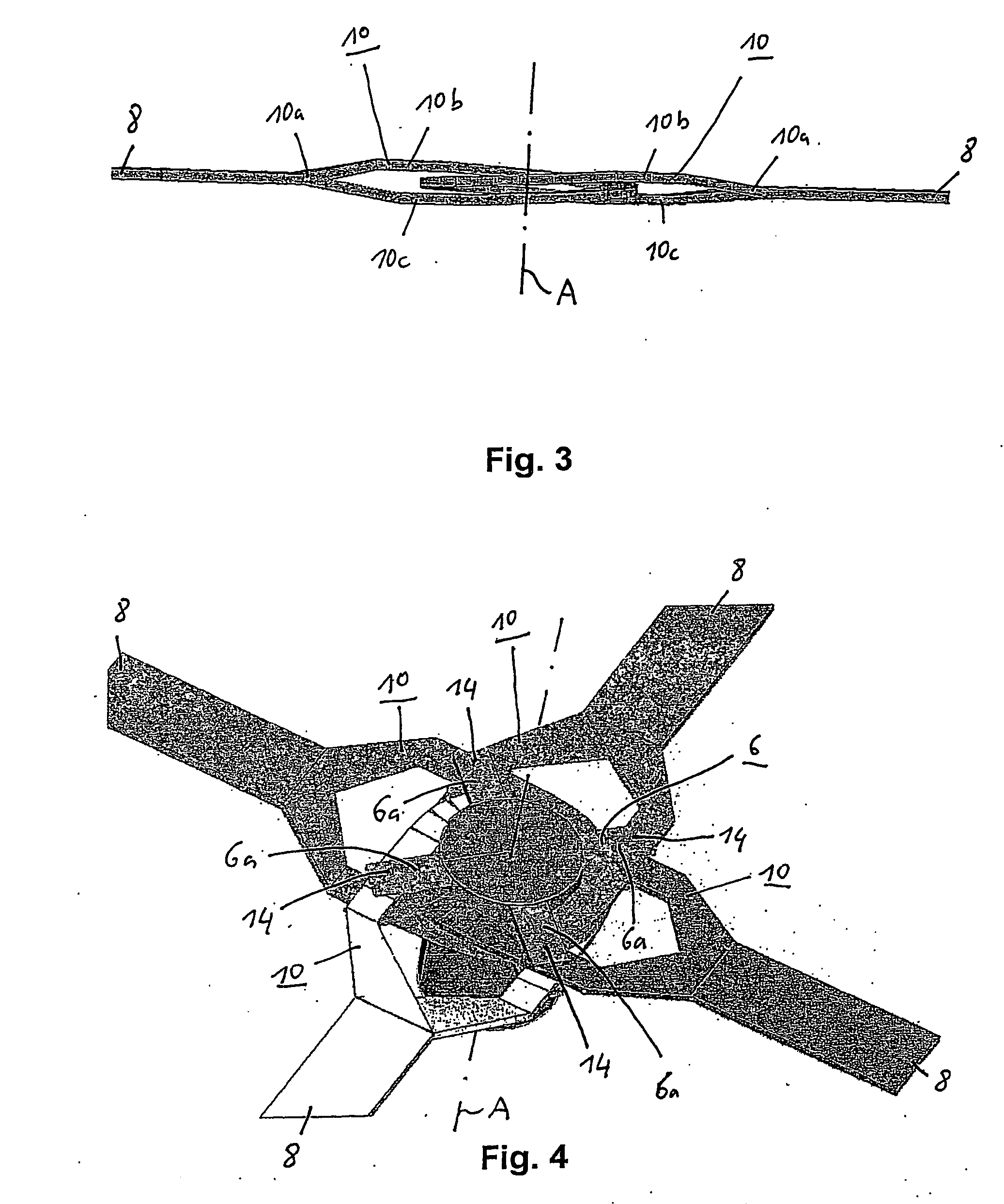
[0045]FIG. 4 is a schematic, greatly simplified perspective depiction of a rotor according to the present invention in accordance with a This version largely corresponds to that of FIGS. 1 to 3. In contrast thereto, however, blade connector loops 10 do not possess a joining tab, and rotor-head star 6 is disposed at an offset of approx. 45 degrees as compared with FIG. 1. Blade connector loops 10 are joined at an overlap region of their respective loop segments, by way of a respective bolt 14 or another suitable joining means, both nonrotatably to rotor-head star 6 and to one another. Two joining points thus result for each loop 10.

[0046] The rotor according to the present invention is used in a rotorcraft, in particular in a helicopter or a tiltrotor helicopter. A rotorcraft of this kind can have one or more rotors according to the present invention, depending on the configuration.

[0047] The invention is not limited to the exemplifying embodiments above, which serve merely for gen...


PUM


Abstract

A hingeless rotor, in particular for a rotorcraft, comprising: a rotor head, a rotor mast having a rotor axis, a torque-transmission element nonrotatably joined to the rotor mast, at least one rotor blade, and a rotor-head-side rotor-blade connector having a centrifugal-force-discharging blade connector loop, which loop encircles the rotor axis or the rotor mast and is nonrotatably joined to the torque-transmission element.

Description

FIELD OF THE INVENTION [0001] The present invention concerns a hingeless rotor as well as a rotorcraft having such a rotor. DESCRIPTION OF RELATED ART [0002] Lift-generating rotor blades of a hingeless rotor for a rotorcraft are manufactured predominantly from fiber composite material. During continuous rotor operation, the rotor blades are deflected in various directions and heavily stressed as a result. The rotor blade usually possesses, at its end pointing toward a rotor head, a structural element having a flapwise-soft and lead-lag-soft region that allows motions of the rotor blade in a flapwise direction and a lead-lag direction. The structural element is also referred to as a flex beam. The flapwise-soft and / or lead-lag-soft region of the structural element is referred to overall as a flexurally soft region. In the direction of the longitudinal rotor-blade axis, the structural element is usually configured at its end pointing toward the rotor head with a blade connector that e...

Claims


Application Information

Patent Timeline
Patent Type & Authority Applications(United States)
IPC IPC(8): B64C27/50B64C27/28B64C27/33B64C27/48B64C29/00
CPCB64C27/28B64C27/33B64C27/48B64C29/0033
Inventor BECKER, GEROLDPFALLER, RUPERT
Owner AIRBUS HELICOPTERS DEUT GMBH
Why Eureka
Try Eureka