Optical glucose sensor chip

Inactive Publication Date: 2006-09-07
KK TOSHIBA
View PDF0 Cites 14 Cited by
  • Summary
  • Abstract
  • Description
  • Claims
  • Application Information

AI Technical Summary

Benefits of technology

[0014] wherein the glucose sensing membrane comprises a color developer, a first enzyme which oxidizes or reduces glucose, a second enzyme which generates a substance for developing the color developer by reacting with a product of the first enzyme, a film-forming polymer compound, and a cross-linking polymer compound.

Problems solved by technology

However, the following problems arise since an extraction medium containing water is used in the iontophoresis method.

Method used


Image

  • Optical glucose sensor chip
  • Optical glucose sensor chip
  • Optical glucose sensor chip

Examples


first embodiment

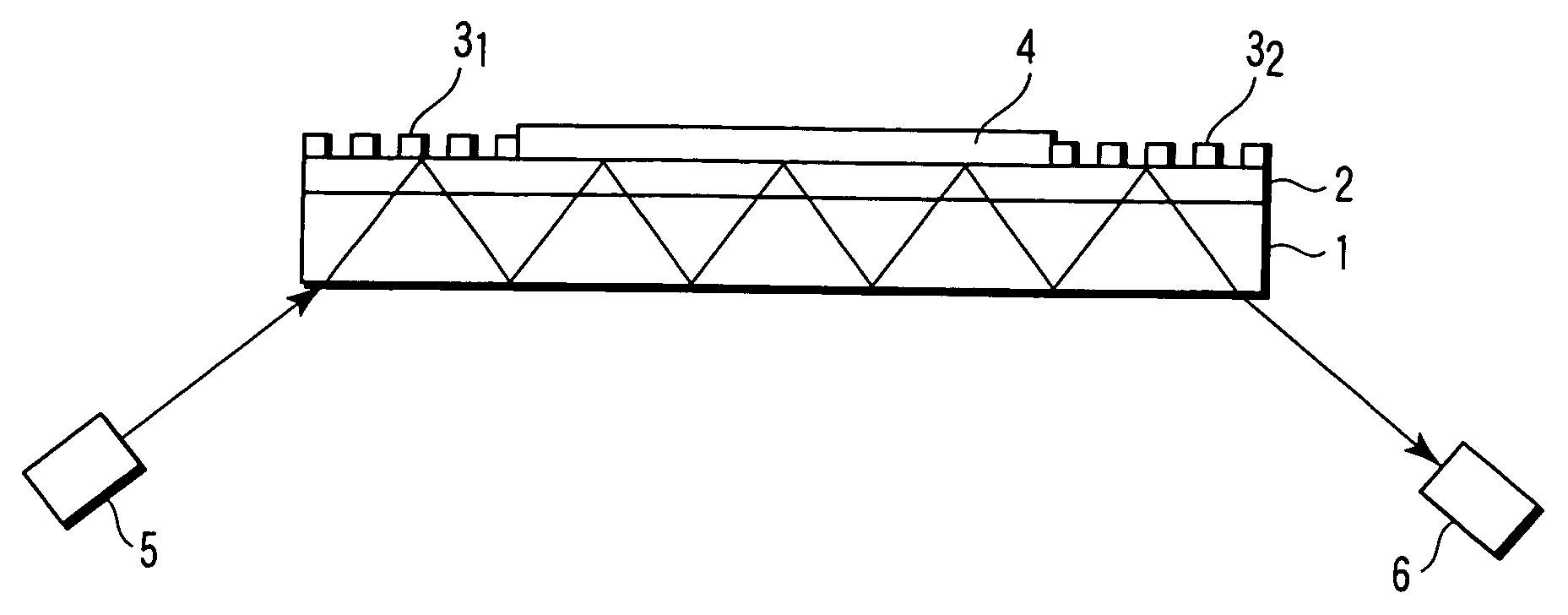
[0027]FIG. 1 is a cross sectional view showing a glucose sensor chip according to a first embodiment of the invention.

[0028] A glass substrate 1 has a SiO2 surface layer 2 with a thickness of, for example, 3 nm or more on the major surface. First and second gratings 31 and 32 as first and second optical elements, respectively, are formed at near both ends of the SiO2 surface layer 2. The fist grating 31 impinges a light into the substrate 1. The second grating 32 emits the light from the substrate 1 to the outside. The first and second optical elements may be replaced with prisms. The first and second gratings 31 and 32 are made of, for example, titanium oxide having a higher refractive index than the SiO2 surface layer 2. A protective layer (not shown) having a lower refractive index than the refractive indices of the fist grating 31 and second grating 32 may be formed so as to cover the first and second gratings 31 and 32. The protective layer is made of, for example, a fluorinat...

second embodiment

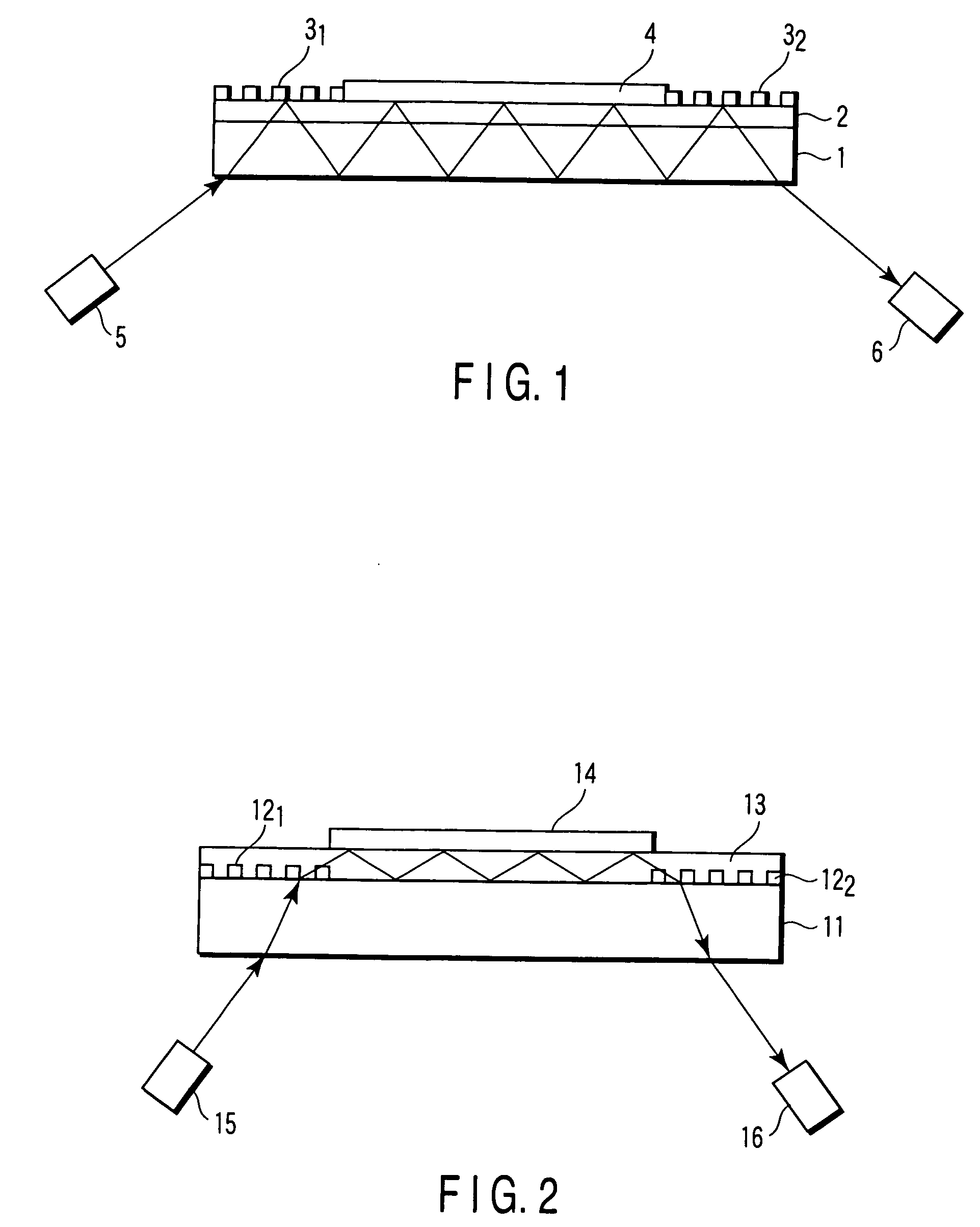
[0043]FIG. 2 shows a cross-sectional view of an optical sensor chip according to a second embodiment of the invention.

[0044] First and second gratings 121 and 122 as first and second optical elements, respectively, are formed at near both ends on the major surface of a glass substrate 11. The first grating 121 impinges a light into the substrate 11. The second grating 122 emits the light from the substrate 11 to the outside. The first and second gratings 121 and 122 are made of, for example, titanium oxide having a higher refractive index than the substrate 11. A light-reflecting waveguide layer 13 made of a thermosetting or light-curable resin having a higher refractive index than the substrate 11 is formed on the major surface of the substrate 11 including the first and second gratings 121 and 122. The major surface of the light-reflecting waveguide layer 13 is formed to be parallel to the major surface of the substrate 11.

[0045] A glucose sensing membrane 14 is formed on the po...

example 1

[0061] Mixed and stirred to prepare 4000 μL of a coating solution for forming a glucose sensing membrane were 1436 μL of isopropyl alcohol (IPA), 956 μL of pure water, 210 μL of phosphate buffer solution (0.01 mol / L, pH 6.0), 60 μL of isopropyl alcohol solution (1% by volume) of polyethyleneglycol, 600 μL of isopropyl alcohol solution of 3,3′,5,5′-tetramethylbenzidine (TMBZ: 1 mg / mL), 640 μL of aqueous solution (2% by weight) of carboxymethyl cellulose, 8 μL of aqueous solution (1% by weight) of a cross-linking polymer (a copolymer of 2-methacryloyloxyethyl phosphorylcholine and butyl methacrylate), 0.67 mg / mL of an aqueous peroxidase (POD) solution (dissolved in 0.01 mole / L of phosphate buffer solution, pH 6.0), and 5.33 mg / mL of an aqueous glucose oxidase (GOD) solution (dissolved in 0.01 mole / L of phosphate buffer solution, pH 6.0).

[0062] Subsequently, a non-alkaline glass substrate having a SiO2 surface layer with a thickness of 10 nm on the major surface and a refractive index...


PUM

PropertyMeasurementUnit
thicknessaaaaaaaaaa
thicknessaaaaaaaaaa
thicknessaaaaaaaaaa

Abstract

An optical glucose sensor chip comprises a glass substrate, a first optical element formed on a major face of the substrate for impinging light into the substrate, a second optical element formed on the major face of the substrate for emitting the light to the outside, and a glucose sensing membrane formed on the major face of the substrate situated between the first and second gratings. The glucose sensing membrane comprises a color developer, a first enzyme for oxidizing or reducing glucose, a second enzyme for generating a substance for developing the color developer by reacting with a product of the first enzyme, a film-forming polymer compound, and a cross-linking polymer compound.

Description

CROSS-REFERENCE TO RELATED APPLICATIONS [0001] This application is based upon and claims the benefit of priority from prior Japanese Patent Applications No. 2005-060441, filed Mar. 4, 2005; and No. 2005-101375, filed Mar. 31, 2005, the entire contents of both of which are incorporated herein by reference. BACKGROUND OF THE INVENTION [0002] 1. Field of the Invention [0003] The invention relates to an optical glucose sensor chip. [0004] 2. Description of the Related Art [0005] An optical glucose sensor chip for low invasive blood glucose measurement has been developed for indirect measurements of blood glucose levels by extracting body fluids from subcutaneous tissues. The sensor chip has a structure comprising a glass substrate, a first grating formed on the surface of the substrate for introducing a light into the substrate, a second grating formed on the surface of the substrate for emitting the light from the substrate, and a glucose sensing membrane formed on the surface of the s...

Claims


Application Information

Patent Timeline
Patent Type & Authority Applications(United States)
IPC IPC(8): G01N21/00
CPCA61B5/14532A61B2562/0295C12Q1/54G01N21/552
Inventor UEMATSU, IKUOTONO, ICHIROOOMIYA, KAYOKO
Owner KK TOSHIBA
Why Eureka
Try Eureka