Multiple layer laminate

a laminate and multi-layer technology, applied in the field of multi-layer laminates, can solve the problems of complicated adhesion of printing inks or inks

Inactive Publication Date: 2006-09-07
LANDQUART +1
View PDF8 Cites 87 Cited by
  • Summary
  • Abstract
  • Description
  • Claims
  • Application Information

AI Technical Summary

Benefits of technology

[0031] The core of the invention therefore consists in the surprising discovery that paper layers and thermoplastic layers, in spite of their very different chemical behavior (industrial thermoplastic versus cellulose) can be partly fused to one another, an extremely stable and intimate bond forming between paper layer and plastic layer. In this context, fusion means that the thermoplastic flows around the cellulose and embeds this as a matrix. While in fact laminates according to the prior art using reactive adhesives or solvent-based adhesives as adhesion promoter between paper and plastic layer have the problem of delamination in high-stress uses, such as, for example, as packaging material, label material, covering material or envelope material and in particular in the case of the extremely high-stress use as bank notes, this can be prevented by a (multiple layer) laminate according to the invention. The laminate according to the invention provides a bond by virtue of the fact that uppermost layers of the plastic layer are directly fused to lowermost layers of the paper layers, i.e. that the fibers of the paper layers are at least partly embedded in a plastic matrix. The resulting penetration zones in the respective boundary regions between plastic layer and paper layers are adjusted so that the plastic partly penetrates the papers layer but without extending completely to that surface of the paper layer(s) which faces away from the plastic layer. This ensures that the haptic properties of the paper are retained on one side of the resulting print substrate, and that the printing properties of the multiple layer laminate or print substrate are likewise substantially retained on the other side. If in fact plastic penetrates the paper substrate completely to the surface or close to the surface, not only does the handle change but also the porosity (this leads, so to speak, to a seal), which may considerably complicate the adhesion of printing inks or inks and may facilitate the abrasion thereof.
[0063] The multiple layer laminate according to the invention or the print substrate according to the invention has the unusual advantage that, in spite of appearance and handle like paper, it offers the possibility of incorporating additional information as security features, in particular security features in the form of or incorporated in windows.

Problems solved by technology

If in fact plastic penetrates the paper substrate completely to the surface or close to the surface, not only does the handle change but also the porosity (this leads, so to speak, to a seal), which may considerably complicate the adhesion of printing inks or inks and may facilitate the abrasion thereof.

Method used


Image

  • Multiple layer laminate
  • Multiple layer laminate
  • Multiple layer laminate

Examples


example 1

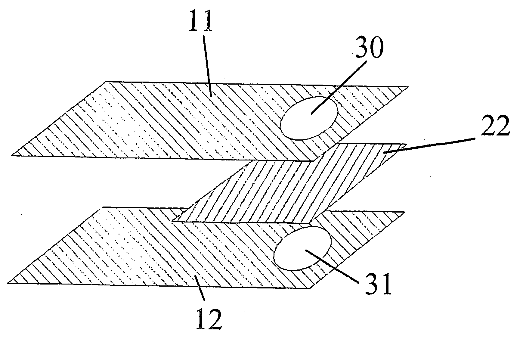
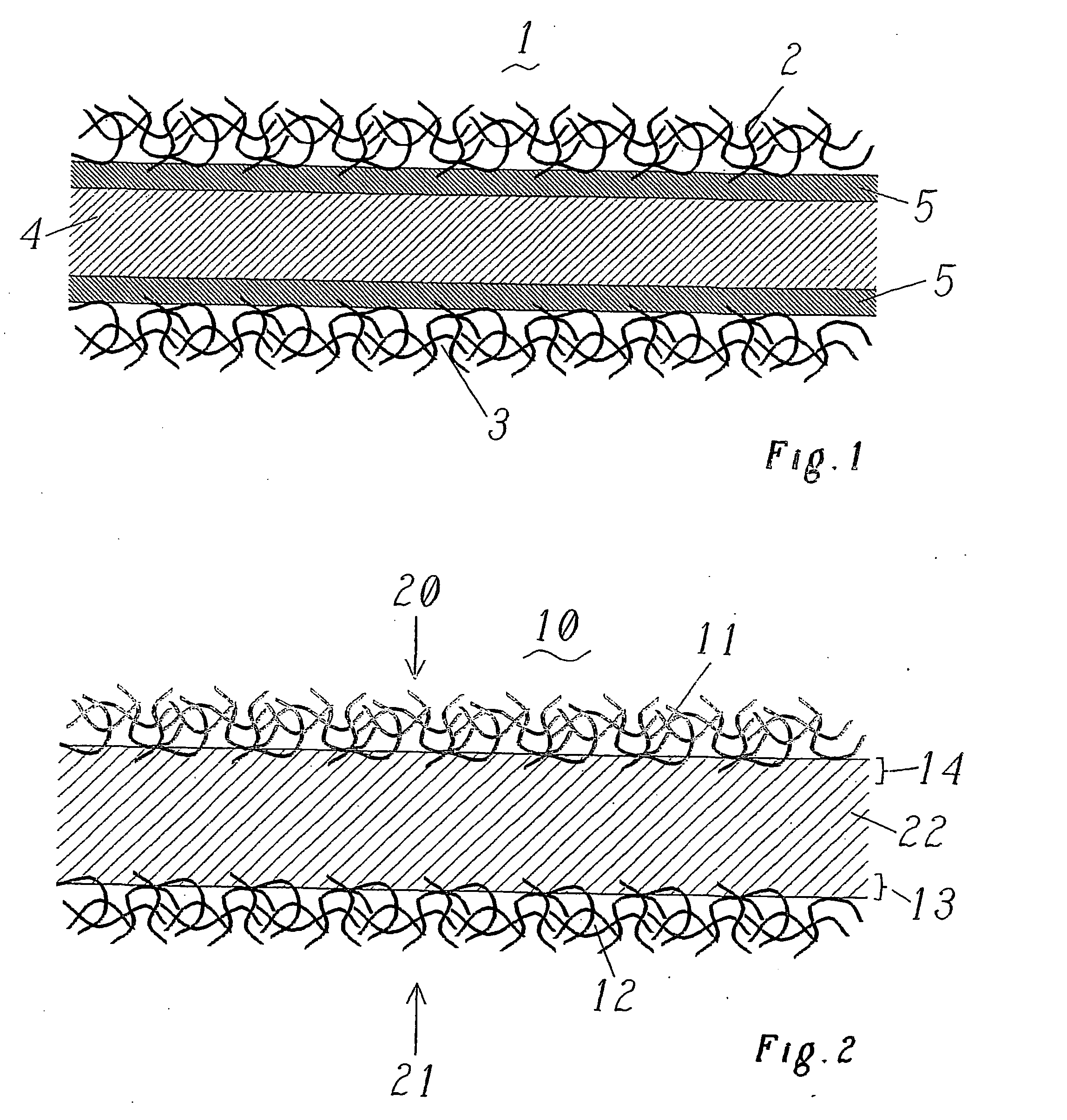
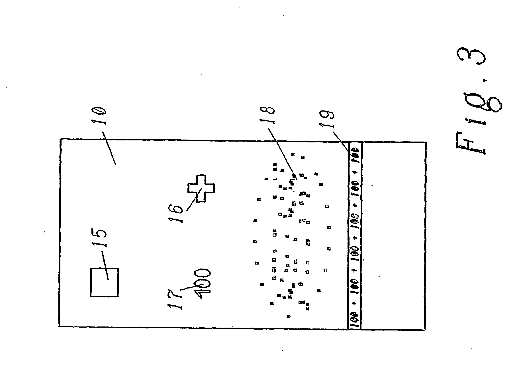
[0142] 20 mm×100 mm samples of paper A were cut out, and a hole of 5 mm diameter was punched out in each case at one end of each piece. A piece of polymer film measuring 20 mm×40 mm×0.1 mm was then cut out and was placed between the two paper layers A, the two paper layers having been placed one on top of the other in such a way that the holes coincided (cf. FIG. 12). This layer structure was initially placed between two polyimide films in order to prevent adhesion to the copper plates of the press. The compression was then carried out for 2 min at 0.5 MPa for the various polymers at the following temperatures: Grilamid® TR 90 LX: 155° C. and 200° C., Surlyn® K: 125° C., Surlyn® Na: 125° C., nylon 11: 155° C. and 200° C., poly(ethylene-co-methyl acrylate): 125° C.

[0143] In all cases, a strong bond was obtained between the paper layers and the polymer. The two regions of the paper which were not bonded by the polymer layer were torn apart (cf. FIG. 13) this led in each of the cases ...

example 2

[0144] Example 1 was repeated, except that a larger piece of Grilamid® TR 90 LX measuring 24 mm×44 mm×0.1 mm was cut out. Once again, this piece was placed between two paper layers comprising paper A, a small region of the polymer film projecting in each case beyond the edge of the paper layers (FIG. 14). The presence of the resulting fusion region 23 in the region of the edge increased the tear resistance (particularly the initiation of the tear) of the corresponding multiple layer laminate dramatically when compared with example 1.

example 3

[0145] Example 1 was repeated, but windows having a diameter up to 16 mm were produced instead of a window of 5 mm. In all cases, satisfactory multiple layer laminates having excellent mechanical properties were obtained.


PUM

PropertyMeasurementUnit
temperatureaaaaaaaaaa

Abstract

The invention relates to a multiple layer laminate such as a printing carrier, especially in the form of antifalsification paper such as bank notes. Said multiple layer laminate or more precisely the printing carrier comprises at least one plastic layer ( 22 ) having an upper side ( 20 ) and a lower side ( 21 ), an upper paper layer ( 11 ) which is connected to the upper side ( 20 ) of the plastic layer ( 22 ), and optionally a lower paper layer ( 12 ) which is connected to the lower side ( 21 ) of the plastic layer ( 22 ). The aim of the invention is to achieve an especially intimate connection between the individual layers, with simultaneously good printability and with similar haptic characteristics such as those of pure paper carriers. To this end, a thermoplastic polymer material is used as the plastic layer ( 22 ), and the connection between the paper layers ( 11, 12 ) and the plastic layer ( 22 ) is ensured, essentially without additional bonding agents, by means of penetration regions ( 13, 14 ) in which parts of the plastic layer ( 22 ) are melted with the mass of fibre composite of the paper layers ( 11, 12 ). To this end, the penetration regions ( 13, 14 ) essentially do not extend to the surfaces of the paper layers opposing the plastic layer ( 22 ).

Description

FIELD OF THE INVENTION [0001] The present invention relates to a multiple layer laminate which can be used, for example, as print substrates, in particular as security paper, but also as packaging material, covering material, card substrate, etc. The multiple layer laminate comprises at least one plastic layer having a top and a bottom, an upper paper layer bonded to the plastic layer and present on the top of the plastic layer, and optionally a lower paper layer bonded to the plastic layer and present on the bottom of the plastic layer. PRIOR ART [0002] Combinations of paper and plastic in a laminate have a variety of uses. Particularly, the resistance of paper is increased by such a laminate (tensile strength, resistance to soiling, etc.). Typical uses of such laminates are, for example, packaging materials, printed or unprinted, covering materials, such as tablecloths, inlays for drawers, etc., gift-wrapping paper, etc. However, such laminates are also used as print substrates, f...

Claims


Application Information

Patent Timeline
Patent Type & Authority Applications(United States)
IPC IPC(8): B32B3/10B32B27/10D21H27/36
CPCB32B27/10Y10T428/24322B42D25/29D21H27/36B32B2307/75B32B2398/20B32B2554/00
Inventor GROB, JAKOBSMITH, PAULFELDMAN, KIRILL
Owner LANDQUART
Why Eureka
Try Eureka