
Electrical contacts having solder stops

a technology of solder stops and electrical contacts, which is applied in the direction of sustainable manufacturing/processing, coupling device connection, and final product manufacturing, etc. it can solve the problems of reduced electrical performance of electrical connections between, reduced integrity of mechanical connections between electrical contacts and printed circuit boards, and reduced solder volume, so as to prevent solder wicking and prevent solder wicking. , the effect of preventing the wicking of solder

Active Publication Date: 2006-09-07
SAMTEC
View PDF45 Cites 17 Cited by
  • Summary
  • Abstract
  • Description
  • Claims
  • Application Information

AI Technical Summary

Benefits of technology

[0005] The reduction in the amount of solder has the following disadvantageous effects: (a) causes a reduction in the electrical performance of the electrical connection between the electrical contact and the printed circuit board; (b) causes a reduction in the integrity of the mechanical connection between the electrical contact and the printed circuit board; (c) hinders mating of the electrical contact with the printed circuit board; and (d) reduces the aesthetics of the completed mechanical connection.

Problems solved by technology

The reduction in the amount of solder has the following disadvantageous effects: (a) causes a reduction in the electrical performance of the electrical connection between the electrical contact and the printed circuit board; (b) causes a reduction in the integrity of the mechanical connection between the electrical contact and the printed circuit board; (c) hinders mating of the electrical contact with the printed circuit board; and (d) reduces the aesthetics of the completed mechanical connection.
A problem with these techniques is that it is hard to accurately plate the additional layer such that nickel layer is exposed in a location that is most effective for preventing the wicking of the solder.
This problem increases the cost of production of any contact that uses the above-described techniques.
An additional problem with these techniques is that exposed nickel is not a very effective anti-wicking material.
Thus, the flux reduces the effectiveness of the oxidized nickel as an anti-wicking material.
A problem with this technique is that the hole in the contact acts to degrade any electrical signal traveling through the contact and to degrade the mechanical strength of the contact.
Another problem with this technique is the cost of the secondary process of punching a hole during manufacturing of the contact.
A problem with this technique is that it is very costly because of the materials and processes used.
Some problems with this technique are the cost associated with the additional assembly step and the cost of the solder mask.
Another problem with this technique is that not all electrical connectors are arranged such that enough space is available to add the tape.
A problem with this technique is that an additional assembly step is required, which increases the time and labor costs for producing a contact.
Another problem with this technique is that it will add extra height to the electrical connector, which will make it unsuitable in situations were an electrical connector having a low profile is needed.
A problem with this technique is that an effective anti-wicking barrier is not created because the opening into which the tail is pressed does not conform precisely to the circumference of the contact.
Another problem with this technique is that it is difficult to apply this technique to SMT (Surface Mount Technology) connectors because there is not sufficient space to add the plastic.
Other problems with the above techniques are that excessive materials can inadvertently be used and that the materials can be inadvertently removed during post reflow cleaning.
Further, these materials may interfere with the formation of a solder joint.

Method used


Image

  • Electrical contacts having solder stops
  • Electrical contacts having solder stops
  • Electrical contacts having solder stops

Examples


Embodiment Construction

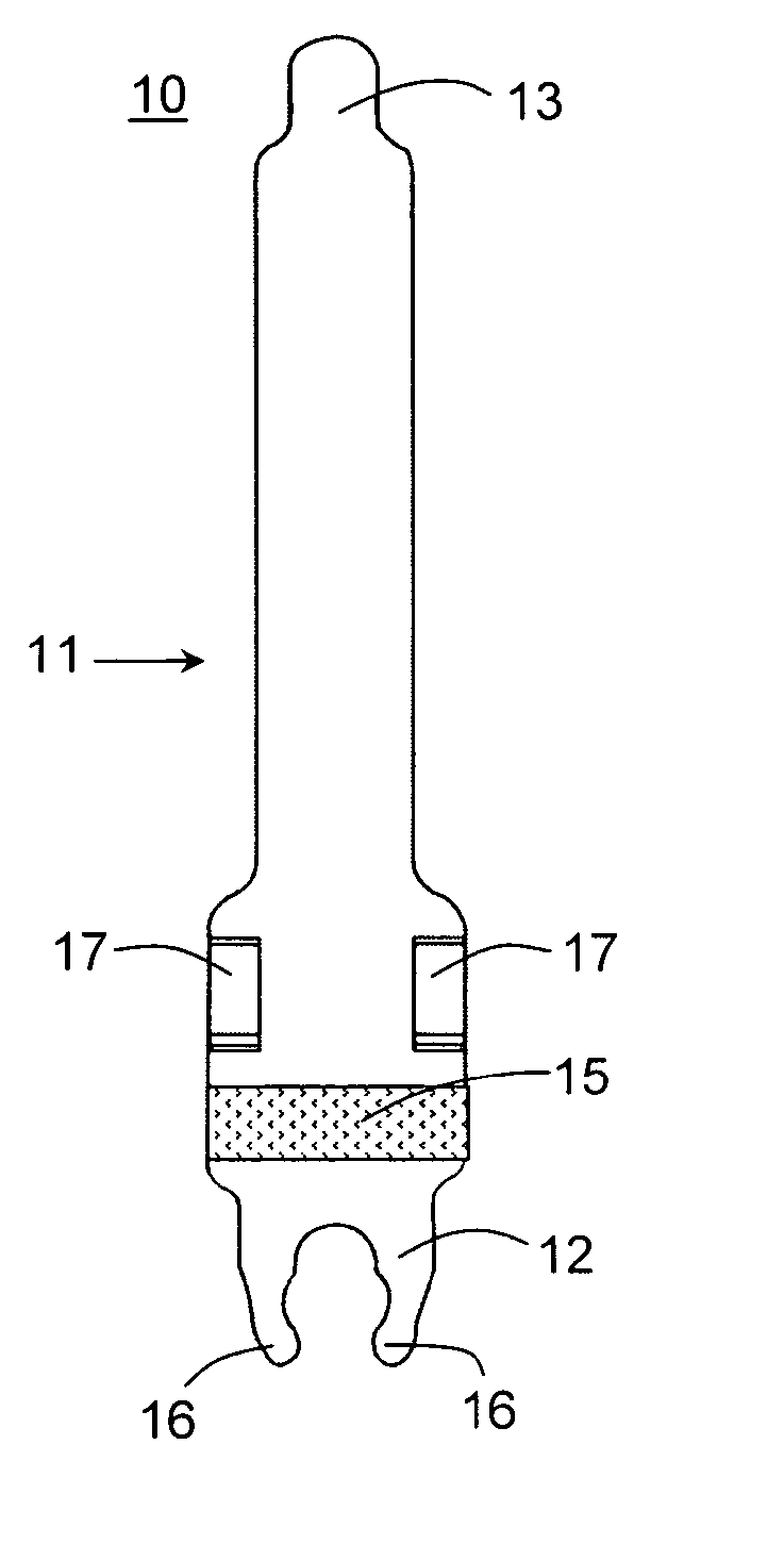
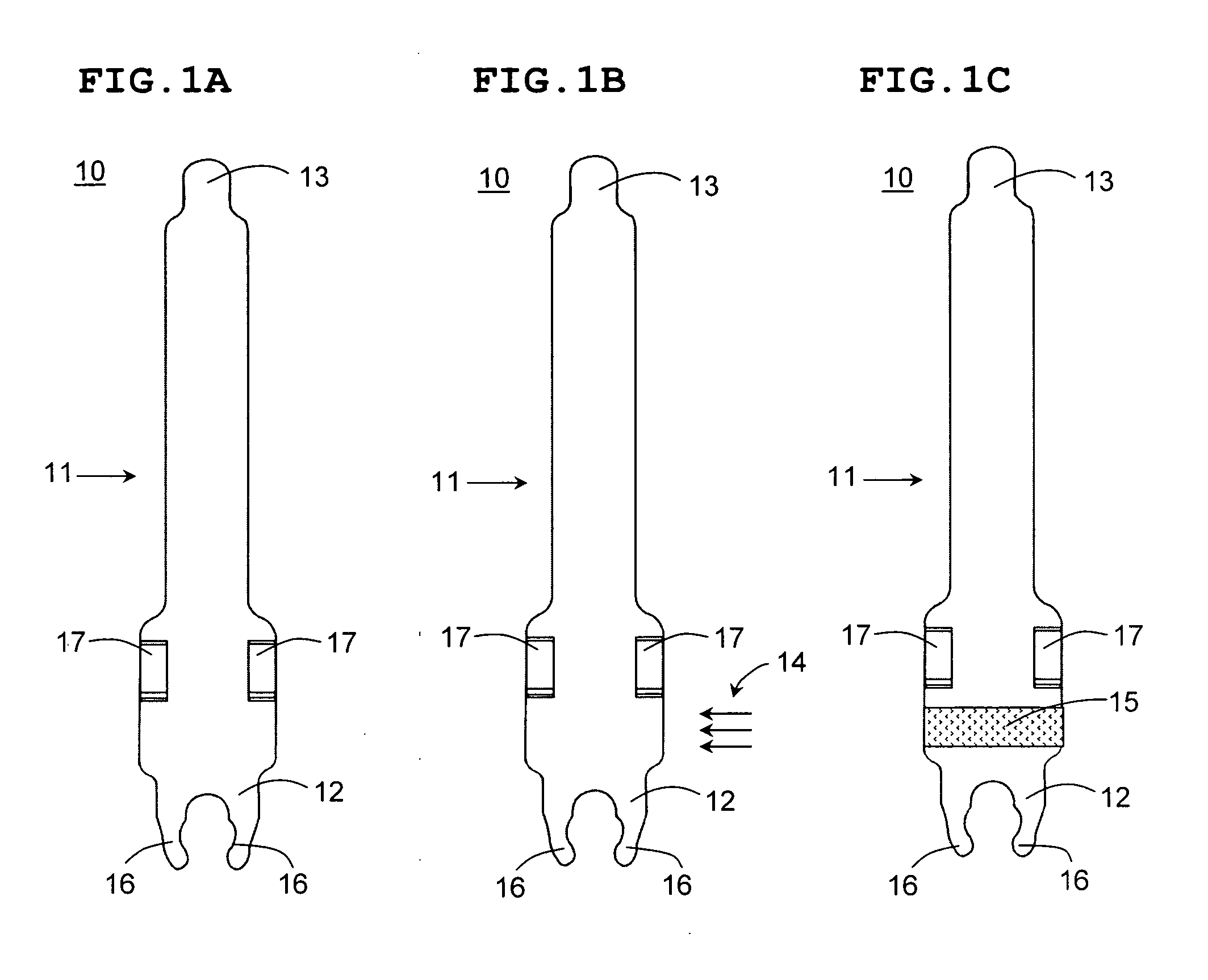
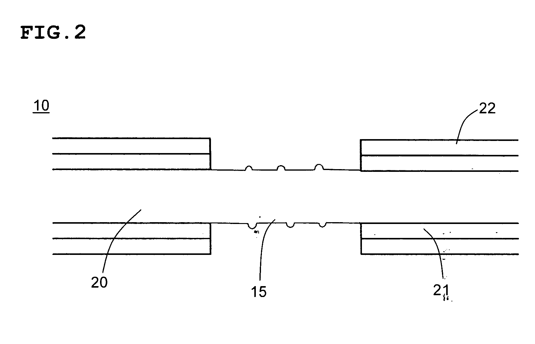
[0053]FIGS. 1A-1C illustrate a method of manufacturing, according to a first preferred embodiment of the present invention, an electrical contact 10 according to a second preferred embodiment of the present invention. FIG. 2 illustrates a close-up sectional view of an anti-wicking region 15 of the electrical contact 10.

[0054]FIG. 1A illustrates the electrical contact 10 having a contact body 11. The contact body 11 includes a contact tail 12 and a contact head 13. As shown in FIG. 1A, the contact tail 12 includes arms 16 for holding a fusible material, such as solder or a solder member (not shown). However, other arrangements for attaching solder to the contact tail 12 could also be used for attaching the fusible material in the form of, for example, solder balls or solder charges. Further, the contact tail 12 need not include any arrangement for holding solder. Instead, the fusible material or solder could be provided on any substrate to which the electrical contact 10 is to be so...


PUM


Abstract

An electrical contact for use in an electrical connector, includes a contact body made of metal and having a contact head, a contact tail, and an anti-wicking region disposed between the contact head and the contact tail arranged to prevent wicking of a fusible material past the anti-wicking region in a direction toward the contact head. The anti-wicking region is defined by one of a laser-ablated portion, a laser marking material, a UV marking material, and an ink that is permanently disposed on the contact body.

Description

BACKGROUND OF THE INVENTION [0001] 1. Field of the Invention [0002] The present invention relates to solder stops. More specifically, the present invention relates to solder stops on electrical contacts and to methods of making electrical contacts having solder stops. [0003] 2. Description of the Related Art [0004] As shown in FIG. 6, it is well known in the art to use solder 64 to form an electrical connection between a connection pad 65 on a printed circuit board 66 and the contact tail 63 of an electrical contact 60. When the solder 64 is reflowed to join the contact tail 63 of the electrical contact 60 to the connection pad 65 on the printed circuit board 66, the solder 64 will wick up the length of the contact body 61, which reduces the amount of solder 64 located between the contact tail 63 of the electrical contact 60 and connection pad 65 on the printed circuit board 66. [0005] The reduction in the amount of solder has the following disadvantageous effects: (a) causes a redu...

Claims


Application Information

Patent Timeline
IPC IPC(8): H01R13/02
CPCH01R12/57H01R13/02H01R13/03H01R13/41H01R43/00H01R43/0256H05K3/3426H05K2201/10909H05K2201/10984H05K2201/2081H05K2203/041H01R12/707Y02P70/50
Inventor VICICH, BRIANKOOPMAN, STEVE
Owner SAMTEC
Learn More