Hair dryer with static atomizing device

Inactive Publication Date: 2006-09-14
MATSUSHITA ELECTRIC WORKS LTD
View PDF8 Cites 18 Cited by
  • Summary
  • Abstract
  • Description
  • Claims
  • Application Information

AI Technical Summary

Benefits of technology

[0008] According to the present invention, a sufficient amount of the electrostatically charged microparticle mist having a particle size of 3 nm to 100 nm can be stably supplied to the user's hair. Therefore, it is possible to more efficiently obtain moist hair that is suitable to perform hairstyling or a hair treatment than before.
[0010] In addition, it is preferred that the liquid transport member is made of a flexible material, and connected at its one end to the tank and at its opposite end to the atomizing electrode, thereby transporting the liquid from the tank to the static atomizing electrode according to capillary phenomenon. By use of the flexible liquid transport member, it is possible to improve a degree of freedom of layout of the tank in the hair dryer. In addition, since the liquid transport member uses the capillary phenomenon to transport the liquid, it is possible to more efficiently and stably transport the liquid to the atomizing electrode by help of the liquid head pressure described above.
[0011] It is also preferred that the atomizing electrode has an opening at its one end, which is configured to supply the liquid into a space between the atomizing electrode and the counter electrode, and a size of the opening is determined such that a surface tension of the liquid (e.g., water) at the opening is larger than a liquid head pressure (e.g., water head pressure) applied to the opening by the liquid in the tank full-filled. In this case, the liquid needed to generate the electrostatically charged microparticle mist is exposed to the discharge space through the opening, and undesired leakage of the liquid from the atomizing electrode can be reliably prevented.
[0012] In addition, it is preferred that the housing comprises a pair of mist generation chambers formed at both lateral sides of the airflow channel, in each of which the atomizing electrode and the counter electrode are disposed, and a tank chamber formed at an upper side of the airflow channel to detachably accommodate the tank, which is commonly used to supply the liquid into the mist generation chambers. In this case, since the liquid is supplied from the single tank to the respective atomizing electrodes through the liquid transport members, it is possible to downsize the static atomizing device. In addition, as compared with a case that a plurality of tanks are disposed in the hair dryer such that each of the tanks is connected to one of the atomizing electrodes by a corresponding liquid transport member, there is an another advantage that an operation of replenishing the liquid in the tank becomes easier.
[0014] As another preferred embodiment of the static atomizing device according to the present invention, the static atomizing device is provided with a plurality of atomizing electrodes connected in parallel to a voltage applying unit and counter electrodes; a single tank configured to store the liquid therein; liquid transport members each configured to transport the liquid from the single tank to one of the atomizing electrodes, the voltage applying unit configured to apply a voltage between the atomizing electrodes and the counter electrodes to generate electrostatically charged microparticle mist of the liquid, and resistive elements connected between the voltage applying unit and the atomizing electrodes. In this case, by approximately determining a resistance value of each of the resistive elements, it is possible to control an influence of distances between the atomizing electrodes and the counter electrodes on discharge states therebetween, and stably generate a larger amount of the electrostatically charged microparticle mist. In addition, there are another advantages of reducing a generation amount of ozone and prevent the occurrence of abnormal discharge.

Problems solved by technology

However, the very fine water particles are easily vaporized when contacting a hot air supplied from the air outlet.

Method used


Image

  • Hair dryer with static atomizing device
  • Hair dryer with static atomizing device
  • Hair dryer with static atomizing device

Examples


Embodiment Construction

[0030] A hair dryer with a static atomizing device of the present invention is explained in details according to preferred embodiments, referring to the attached drawings.

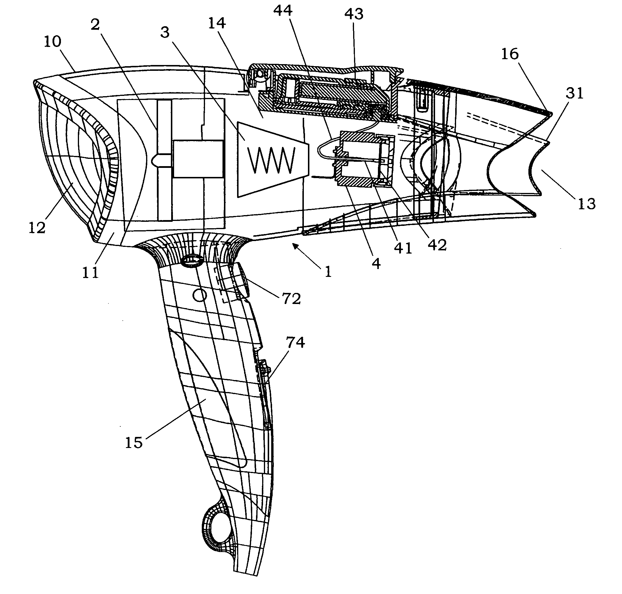
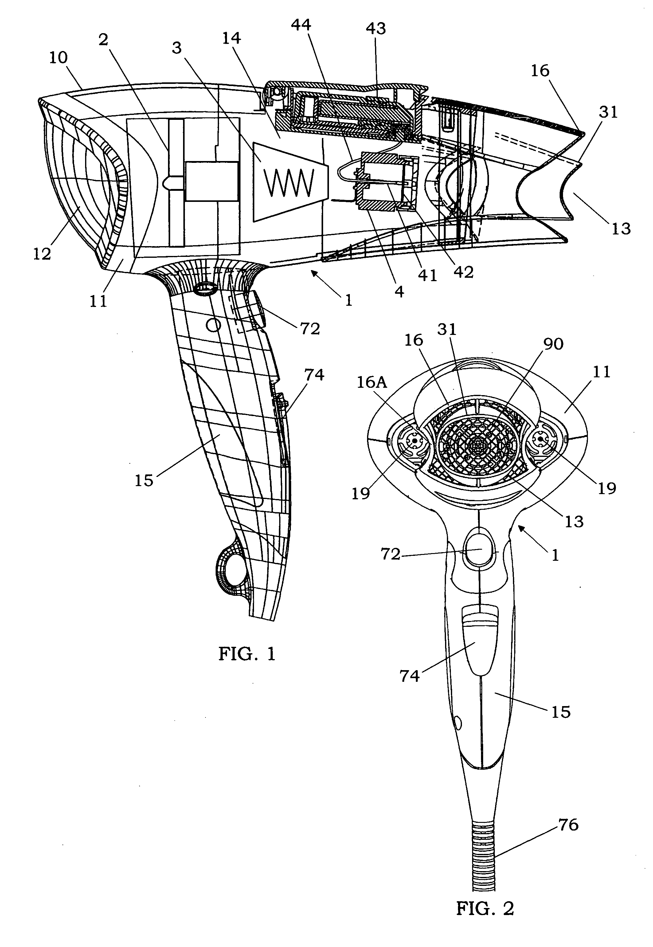
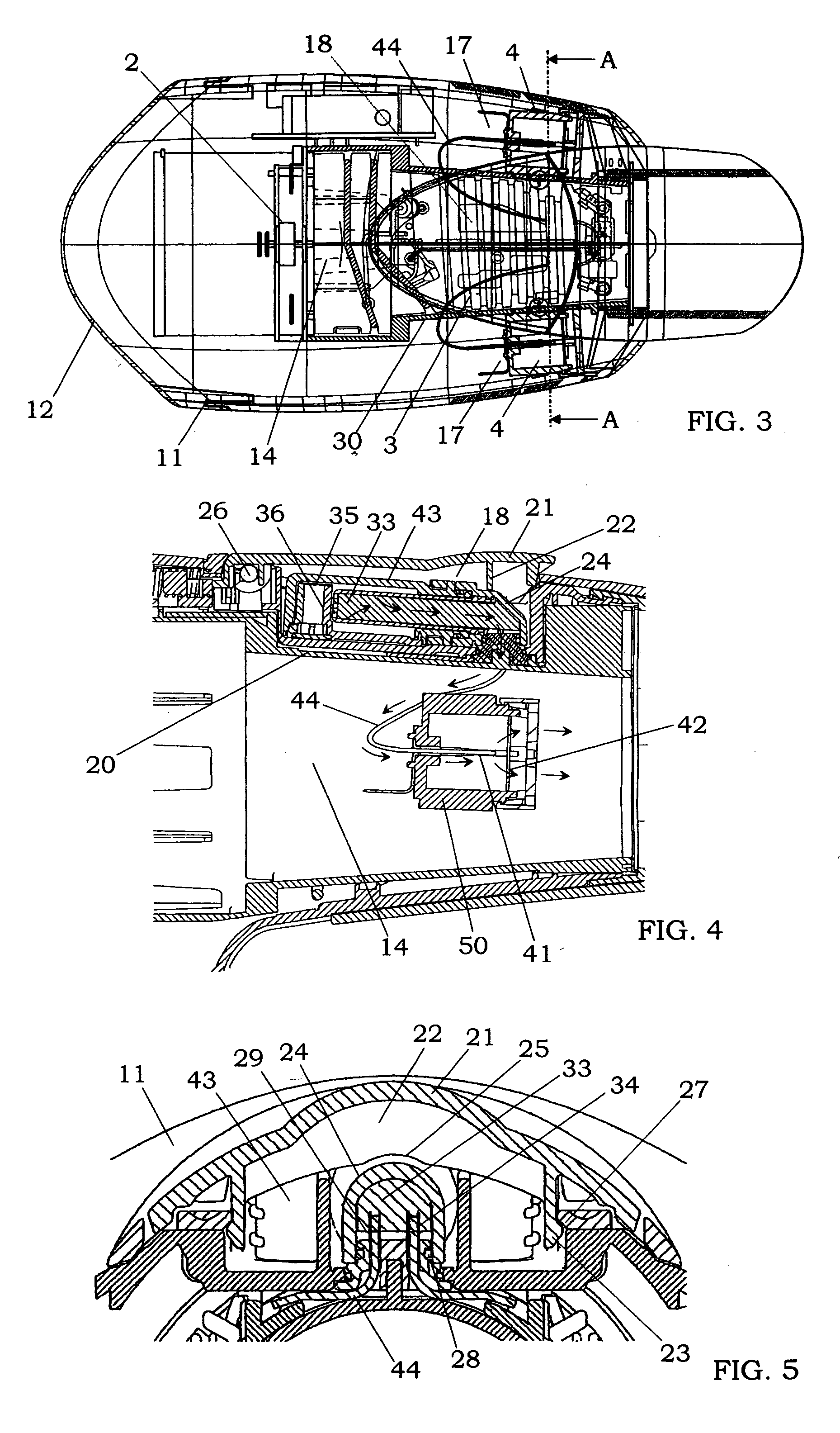
[0031] As shown in FIGS. 1 to 3, the hair dryer 1 of this embodiment has a housing 10 for accommodating a fan 2, a heater 3 and a static atomizing device 4 therein. The housing 10 is mainly composed of a main housing 11 formed in a substantially hollow structure and having an air inlet 12 at its one end, an air outlet 13 at its opposite end, and an airflow channel 14 extending therebetween, and a grip housing 15 extending downward from the main housing 11. In the drawings, the numeral 72 designates a push button formed on the grip housing 15 to switch the fan 2 between ON and OFF states, and switch the hater 3 between ON and OFF states when the fan 2 is in the ON state. The numeral 74 designates a slide button formed on the grip housing 15 to control the airflow amount provided by the fan 2 in a stepwise manner. T...


PUM


Abstract

A hair dryer with a static atomizing device is provided, which has the capability of generating an electrostatically charged microparticle mist of 3 nm to 100 nm. The static atomizing device has a pair of an atomizing electrode and a counter electrode, a tank for storing a liquid such as water; a liquid transport member for transport water from the tank to the atomizing electrode according to capillary phenomenon, and a voltage applying unit. When a high voltage is applied between the atomizing electrode and the counter electrode, while water being supplied to the atomizing electrode through the liquid transport member, the electrostatically charged microparticle mist is generated.

Description

BACKGROUND OF THE INVENTION [0001] 1. Field of the Invention [0002] The present invention relates to a hair dryer, and particularly the hair dryer with a static atomizing device for generating an electrostatically charged microparticle mist of a liquid such as water. [0003] 2. Disclosure of the Prior Art [0004] In the past, a hair dryer with a minus-ion generator has been widely utilized for hair drying, hair styling, and a hair treatment. For example, Japanese Patent Early Publication No. 2002-191426 discloses a hair dryer for providing an airflow containing minus ions. According to this hair dryer, it is possible to effectively prevent that minus ions are trapped by a grid member attached to an air outlet, and achieve a stable supply of the minus ions. [0005] By the way, very fine water particles of about 1 nm derived from the moisture in the air are adhered to the minus ions generated by the minus-ion generator of the above hair dryer. However, the very fine water particles are e...

Claims


Application Information

Patent Timeline
IPC IPC(8): A45D20/12
CPCA45D20/12A45D2001/008A45D2200/202B05B5/03B05B5/0533B05B5/1691B05B5/001
Inventor NAKAGAWA, TAKASHIMATSUI, YASUNORIKODAMA, NAOFUMIYAMAGUCHI, TOMOHIROTAKASHIMA, KIYOSHIHIRAI, TOSHIHISAKAMADA, KENJIITO, KENGOOKAWA, KAZUMIISAKA, ATSUSHIMURASE, SHINYAHIRAI, KISHIKO
Owner MATSUSHITA ELECTRIC WORKS LTD
Why Eureka
Try Eureka