
Process for producing high silicate glass and high silicate glass

a technology of high silicate glass and high silicate glass, which is applied in glass tempering equipment, glass making equipment, manufacturing tools, etc., can solve the problems of high cost and difficulty of upsizing, the melting process has the drawback of requiring a very high temperature, and the uv and ir transmittance cannot be sufficiently increased, so as to achieve high silicate, low cost, and high silicate

Inactive Publication Date: 2006-09-14
JAPAN SCI & TECH CORP
View PDF8 Cites 7 Cited by
  • Summary
  • Abstract
  • Description
  • Claims
  • Application Information

AI Technical Summary

Benefits of technology

[0010] The method for producing high silicate glass is an application of the Vycor method, and heat treatment of borosilicate glass makes it possible to phase-separate the borosilicate glass into an insoluble phase (silicate phase) consisting mainly of SiO2 and a soluble phase (borate phase) consisting mainly of B2O3. According to the producing method of the present invention, the borosilicate glass contains a heavy metal or rare-earth element so that in the phase-separating step, low-valence Fe ions (Fe2+ ions) can be transformed into Fe3+ ions.
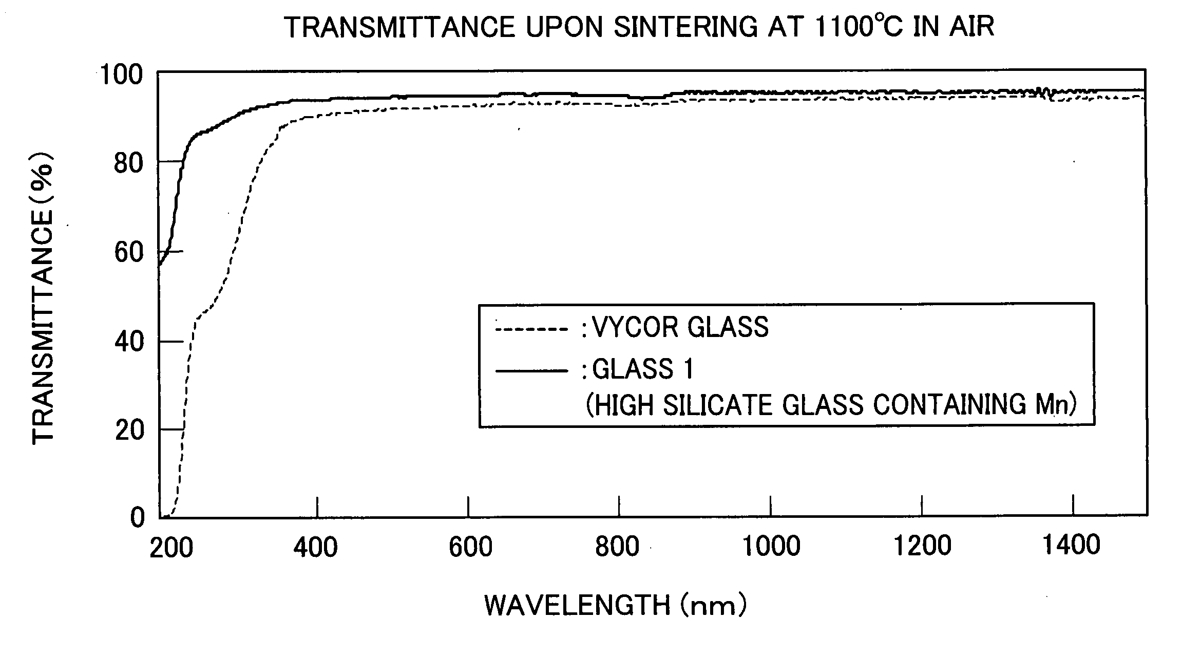
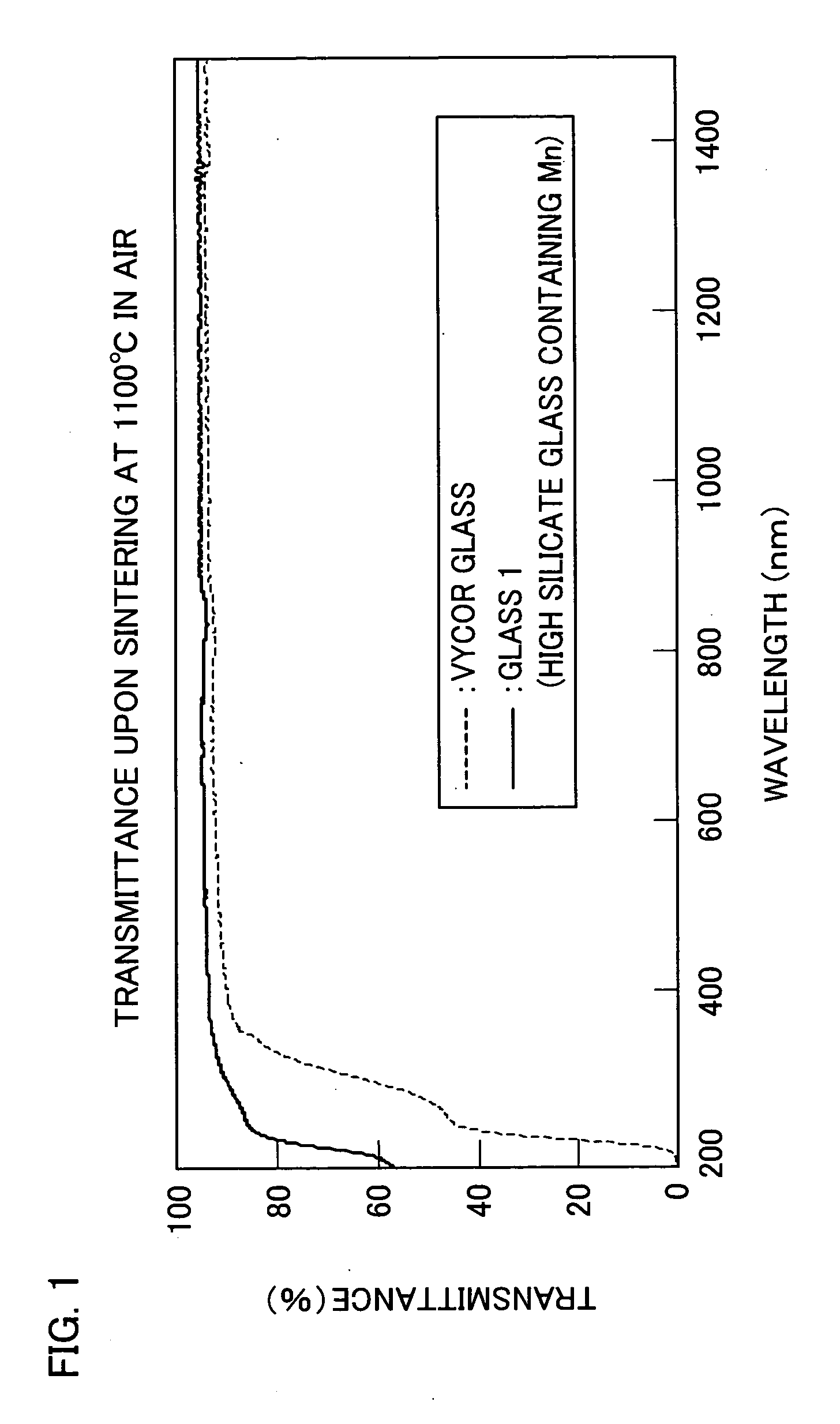
[0031] The foregoing high silicate glass has a higher UV transmittance than the Vycor glass (glass produced by the conventional Vycor method). Therefore, the high silicate glass allows for formation of a complex compound by introducing UV emission photofunctional ions as dopants into the high silicate glass. Thus, the high silicate glass has the possibility of being widely used as various optical materials.

Problems solved by technology

However, these production processes have drawbacks such as extremely high cost and difficulty of upsizing.
Particularly, the melting process has the drawback of requiring a very high temperature (1900° C. or above).
However, the Vycor method causes Fe (iron) ions and water to remain in glass and thus has the problem that UV and IR transmittances cannot be sufficiently increased.

Method used


Image

  • Process for producing high silicate glass and high silicate glass
  • Process for producing high silicate glass and high silicate glass
  • Process for producing high silicate glass and high silicate glass

Examples


example 1

[0061] In Example 1, glass was obtained in the following manner. Commercially available reagents (Na2CO3, H3BO3, SiO2, Al(OH)3, CaCO3, and MnO2) were weighed and mixed so as to achieve a glass composition having Na2O: 7.7 (wt %), CaO: 4.0 (wt %), Al2O3: 2.7 (wt %), MnO2: 0.7 (wt %), B2O3: 33.3 (wt %), and SiO2: 51.7 (wt %). The mixture was melted for four hours at 1400° C. by using a platinum crucible.

[0062] The thus obtained glass was polished, was heated for 40 hours at 590° C. in a heat-treating furnace, and was subjected to phase separation. Thereafter, the phase-separated glass was contained together with 1N nitric acid into an airtight container and was subjected to acid treatment for 24 to 72 hours at 90° C. The acid-treated glass was further sintered for two hours at 1100° C. in the air, thereby producing high silicate glass (hereinafter referred to as “Glass 1”). Measurement was conducted on a transmittance of Glass 1 with a thickness of 1.0 mm.

[0063] As a comparative exa...

example 2

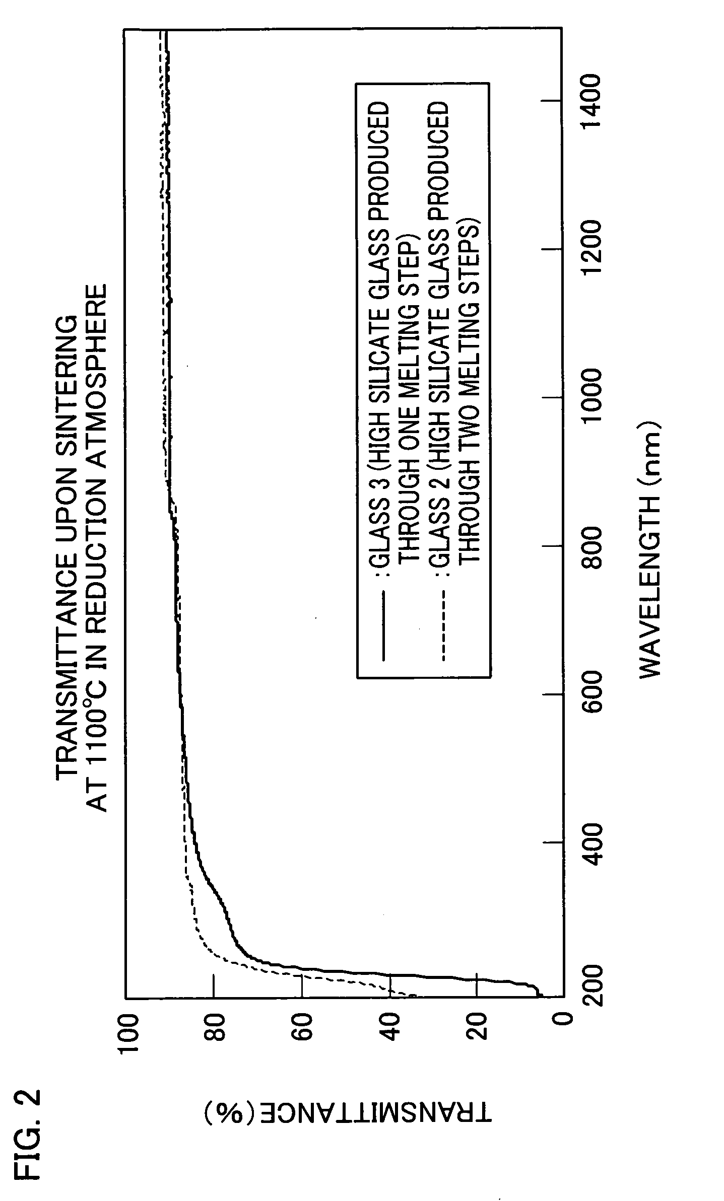
[0066] In Example 2, glass was obtained in the following manner. Commercially available reagents (Na2CO3, H3BO3, SiO2, Al(OH)3, and CaCO3) were weighed and mixed so as to achieve a glass composition of SiO2: 77.5 (wt %), Na2O: 11.5 (wt %), CaO: 6.0 (wt %), and Al2O3: 5.0 (wt %). In a first melting step, the mixture was melted for four hours at 1500° C. by using a platinum crucible. Thereafter, in a second melting step, H3BO3 was added to the mixture so as to achieve a glass composition having 50 parts by weight of H3BO3 per 100 parts by weight of the glass obtained after melting. Then, the mixture was subjected to second melting at 1400° C.

[0067] The thus obtained glass was polished, was heated for 40 hours at 590° C. in a heat-treating furnace, and was subjected to phase-separation. The phase-separated glass was contained together with 1N nitric acid into an airtight container and was subjected to acid treatment for 24 to 72 hours at 90° C. The acid-treated glass was further sinte...

example 3

[0071] In Example 3, glass was obtained in the following manner. Commercially available reagents (Na2CO3, H3BO3, SiO2, Al(OH)3, CaCO3, and CeO2) were weighed and mixed so as to achieve a glass composition of SiO2: 77.5 (wt %), Na2O: 11.5 (wt %), CaO: 6.0 (wt %), Al2O3: 4.0 (wt %), and CeO2: 1.0 (wt %). In a first melting step, the mixture was melted for four hours at 1500° C. by using a platinum crucible. In a second melting step, H3BO3 was added to the mixture so as to achieve a glass composition having parts by weight of H3BO3 per 100 parts by weight of the glass obtained after melting. Then, the mixture was subjected to second melting at 1400° C.

[0072] The thus obtained glass was polished, was heated for 40 hours at 590° C. in a heat-treating furnace, and was subjected to phase-separation. The phase-separated glass was contained together with 1N nitric acid into an airtight container and was subjected to acid treatment for 24 to 72 hours at 90° C., thereby obtaining porous glass...


PUM

PropertyMeasurementUnit
thicknessaaaaaaaaaa
thicknessaaaaaaaaaa
temperatureaaaaaaaaaa

Abstract

The present invention provides: a method for producing high silicate glass which has a low Fe concentration and can achieve a high UV transmittance while retaining advantages of Vycor glass that mass-production at low cost is feasible and that complex formation with various photofunctional ions can be effected; and high silicate glass of a high UV transmittance. For obtaining the above high silicate glass, the method is characterized by comprising the steps of: heating borosilicate glass including a heavy metal or rare-earth element (preferably a high-valence heavy metal or rare-earth element) so as to phase-separate the borosilicate glass; subjecting the phase-separated borosilicate glass to acid treatment so as to elute a metal; and sintering the acid-treated borosilicate glass.

Description

TECHNICAL FIELD [0001] The present invention relates to a method for producing high silicate glass which has a high ultraviolet (UV) transmittance and which can be used as an excimer laser base material, a UV transmission filter, a UV utilization material, and the like. The present invention also relates to high silicate glass which has a high UV transmittance. BACKGROUND ART [0002] Conventionally, quartz glass has been widely used as a UV transmission material. Quartz glass is produced by using a CVD (chemical vapor deposition) process, a melting process, or other processes. However, these production processes have drawbacks such as extremely high cost and difficulty of upsizing. Particularly, the melting process has the drawback of requiring a very high temperature (1900° C. or above). In recent years, a technique for producing a light source such as a UV region laser or a lamp has been established, and quartz glass has been used for various purposes other than infrared optical co...

Claims


Application Information

Patent Timeline
Patent Type & Authority Applications(United States)
IPC IPC(8): C03C15/00C03C3/06C03C4/00
CPCC03C3/06C03C4/0085C03C15/00
Inventor AKAI, TOMOKOCHEN, DANPING
Owner JAPAN SCI & TECH CORP
Learn More