
Process for monitoring and controlling of thermal spray process

Inactive Publication Date: 2006-09-14
DAIMLER AG
View PDF5 Cites 6 Cited by
  • Summary
  • Abstract
  • Description
  • Claims
  • Application Information

AI Technical Summary

Benefits of technology

[0010] It is thus the task of the invention to provide a process which makes possible, for a thermal spray processes with a multi-component spray material, a component-specific or, as the case may be, material-specific measurement of the particle characteristics in the spray stream, and an on-line inspection or control of the spray stream with a simple measuring device.
[0031] The inventive preferred material combinations include those of which the melting points differ by at least 150° C., particularly preferably 200° C., from each other. It was discovered that the separation distinctness of the measurement process improves with increasing melt temperature difference.
[0039] The combination of the information of material distribution and temperature distribution provides a very good image of the quality of the spray flame. Inhomogeneities of the flame can be remedied by follow-up control of the carrier stream or by changing of the material dosing, in particular also only by a supplemented material.

Problems solved by technology

These polymer components exhibit a lower temperature in the spray stream, and the known measurement and control systems fail to measure these low temperatures.
In multi-component spray systems it is very desirable when the values of the components can be individually determined, since one value averaged for all components is only insufficiently or partially, if at all, suitable for process control.
A disadvantage of the above-discussed process is the complex measurement equipment of various partial systems.
It is also not possible to obtain an individual analysis or inspection of the different materials in the spray stream.

Method used


Image

  • Process for monitoring and controlling of thermal spray process
  • Process for monitoring and controlling of thermal spray process

Examples


Embodiment Construction

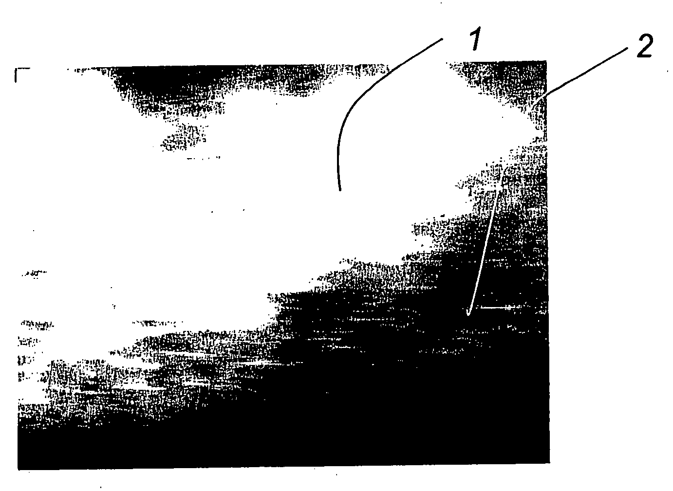
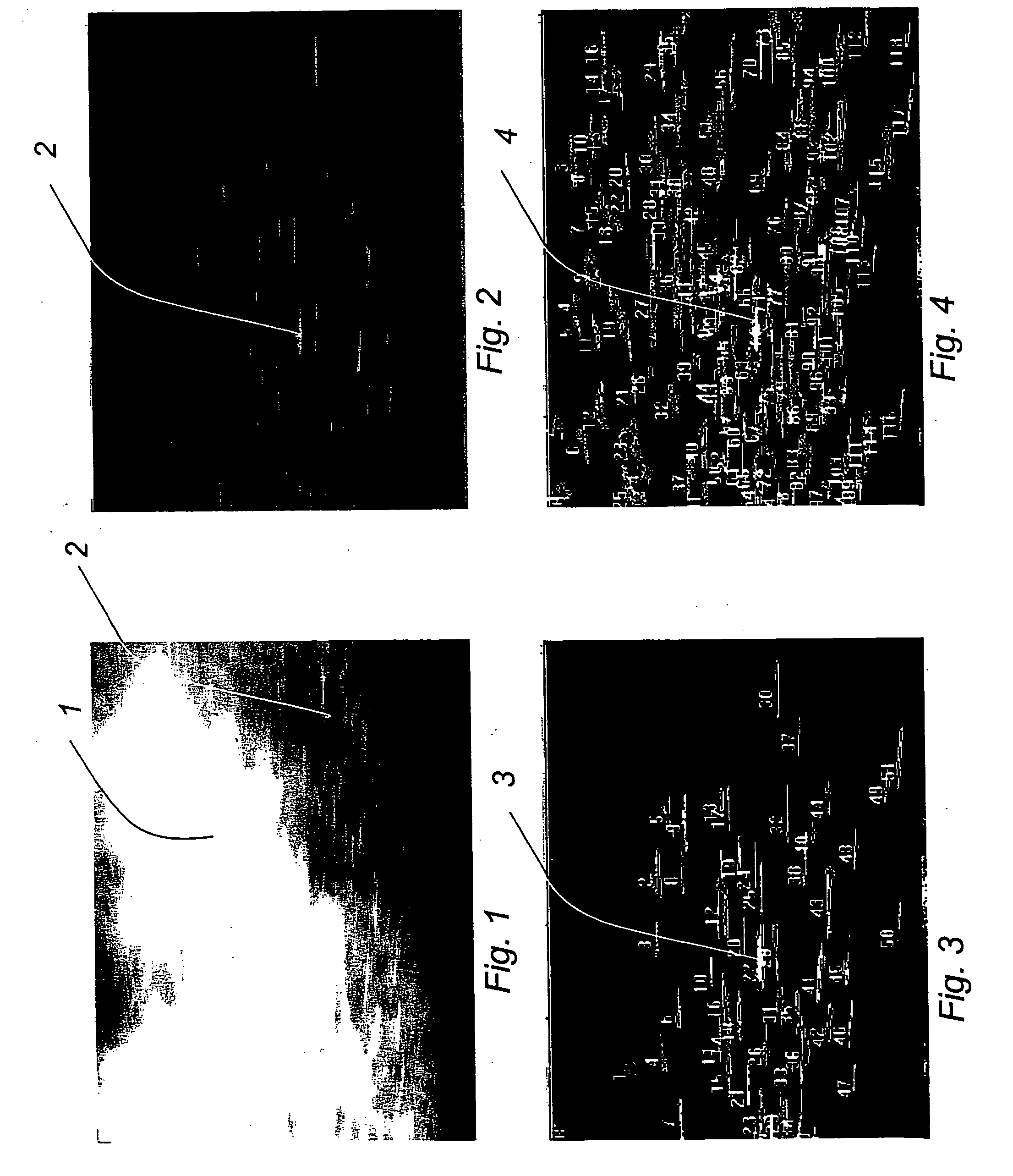
[0051] The background radiation of the spray stream 1, which is comprised essentially of the plasma flame, is determined and subtracted from the image, so that a substantial improvement of the useful measuring information is achieved. Now also in the central area of the spray flame individual particles 2 are clearly recognizable.

[0052] In FIG. 2 and FIG. 3 it is clearly recognizable, that the individual particles can be individually resolved and classified to the individual materials. The represented dash positions or orientations allow a determination of the particle speed of the individual particles.


PUM

PropertyMeasurementUnit
Timeaaaaaaaaaa
Melting pointaaaaaaaaaa
Temperatureaaaaaaaaaa

Abstract

A process for monitoring the spray stream during thermal spraying of spray material, which contains at least two different materials A and B, by means infrared thermography, wherein the thermographic measured values are divided into at least two regions of the radiation intensity and these are assigned or associated to the respective image data for the at least two materials A and B as well as processes for controlling a thermal spray process with spray material multiple materials, wherein the material distribution of at least two materials A and B and their material specific average temperatures and / or radiation intensities within the spray stream are employed as normed values for the spray parameter carrier gas flow through, burner or flame power and / or material dosing.

Description

CROSS REFERENCE TO RELATED APPLICATION [0001] This application claims the benefit of German Application No. DE 10 2005 010 754.0-45 filed Mar. 9, 2005. BACKGROUND OF THE INVENTION [0002] 1. Field of the Invention [0003] The invention concerns an image-producing process for monitoring the spray stream during thermal spraying of a spray material containing at least two different materials A and B, by means of image-producing infrared thermography, in particular material combinations A-with-B of plastic or plastic mixtures with metal alloys, preferably for production of slide layers, friction layers or running-in layers, as well as processes for controlling the spray process by the evaluation of material-specific measured values in the spray stream and adaptation of the spray parameters. [0004] Presently, conventional image-producing processes for controlling or regulating thermal spray processes based on optical processes in the ultraviolet (UV), visible (VIS), or near infrared (near ...

Claims


Application Information

Patent Timeline
IPC IPC(8): B23K9/00B23K9/02
CPCC23C4/12G01J2005/0081
Inventor BOHMISCH, MATHIASHAAS, CORNELIUSHOLDIK, KARLSTEINWANDEL, JURGENZOLLER, ANSGAR
Owner DAIMLER AG
Learn More