Method and apparatus for cooling extruded plastic foil hoses

a technology of extruded plastic foil and hoses, which is applied in the field of method and apparatus for cooling extruded plastic foil hoses, can solve the problems that the cooling speed and evenness of foils cannot always be guaranteed, and achieve the effects of reducing deficiencies, reducing production costs, and increasing foil production productivity

Inactive Publication Date: 2006-09-14
PELCZ ANTAL +1
View PDF4 Cites 2 Cited by
  • Summary
  • Abstract
  • Description
  • Claims
  • Application Information

AI Technical Summary

Benefits of technology

[0005] The primary object of the present invention is to eliminate the deficiencies mentioned above, that is, to create an improved technology whereby the foil product exiting from the extruder nozzle can be cooled down more rapidly, more evenly, and more efficiently than by the traditional solutions mentioned above. A further object is to increase the productivity of foil production, in general, by increasing the foil cooling efficiency.
[0015] However, according to our experiments, the coolant spiral flow consists of layers within a given cross-section as a result of the centrifugal force and the difference of density between cold and hot coolant parts. As commonly known, the density of cold air is higher (therefore it is heavier), thus the centrifugal force has a more intense impact on it, so the cooler layer within a medium flowing along an annular space is always located radially outside in the annular space. Based on the above principles, the apparatus according to the invention operates by feeding a media of different temperatures, e.g. gases, to cylindrical spaces, e.g. into the external ring channel and the internal annular space of the foil hose, advantageously in a counter current, at high speeds, and always tangentially. The initially colder medium if fed tangentially below (in case of a vertical arrangement), so that the rising stream of air resulting from the heat up of the medium should not hinder but rather further assist the spiral medium flow. On the other hand, an initially relatively hotter medium is fed tangentially above to the annular space for the same consideration, so that the descending air stream resulting from its being cooled down should assist the spiral flow of the medium here as well.
[0018] Our experimental results show that the speed of the coolant gas is limited by the strength of the foil hose. Speed difference between the foil and the coolant, however, can be further increased to a surprising degree by feeding the coolant tangentially in accordance with the invention. Furthermore, according to our experiments, centrifugal forces from the spiral coolant flow—affecting the foil hose—also have a favorable impact on the stability of the foil hose, resulting in astonishing extra technological effects.

Problems solved by technology

With the above foil cooling, however, rapid and even foil cooling cannot always be ensured by the air streams exiting through the radial outlets.
This poses a particular problem at higher foil speeds as in such cases there is a relatively shorter time available for cooling; this means that presently foil cooling is a critical phase of the entire foil production technology.
As already referred to above, the maximum applicable foil speed for traditional cooling technologies is about 120 m / min, which is a hindrance to further increases of production.

Method used


Image

  • Method and apparatus for cooling extruded plastic foil hoses
  • Method and apparatus for cooling extruded plastic foil hoses
  • Method and apparatus for cooling extruded plastic foil hoses

Examples


first embodiment

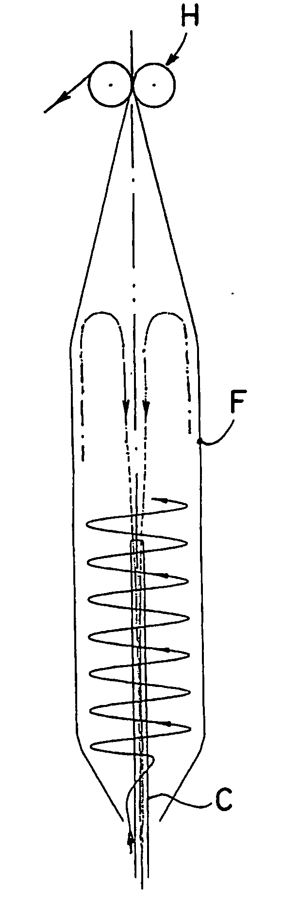
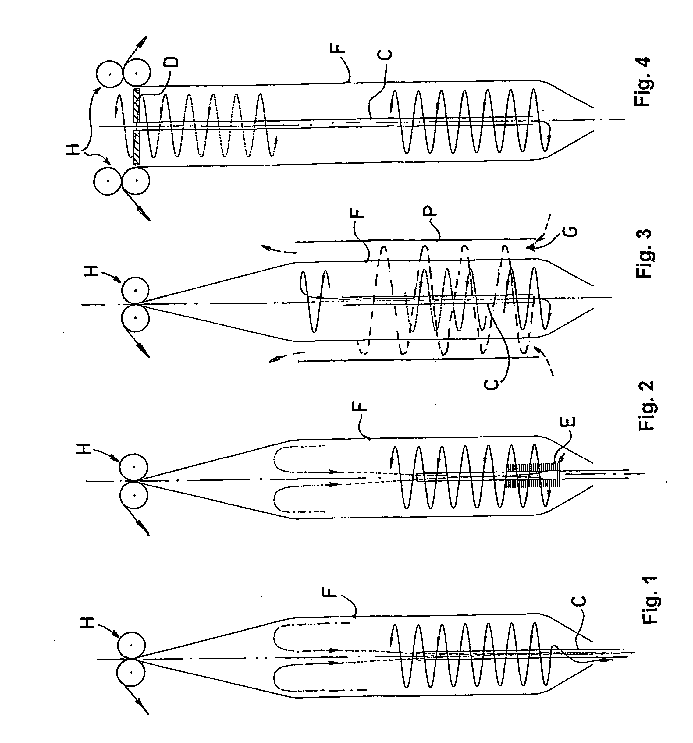
[0027] According to FIG. 1, the cooling technology according to the invention shows an internal cooling of a foil hose F just exiting from an extruder nozzle aperture (not illustrated). As coolant pressurized air is fed in transversally and tangentially (in sharp contrast to traditional solutions of driving it in radially and parallel with the upward direction of progress of the foil). This way, a swirl (rotation) is given to the coolant stream by the tangential inlet, so the coolant stream will flow along a spiral track (indicated by a continuous line) in accordance with our invention, within a cylindrical inner space of the foil hose F, due to the centrifugal force affecting the coolant stream along the internal surface of the foil hose F, and density and pressure differences between various parts of the coolant stream. Thereby the speed difference between the foil hose progressing upwards to a known drawing-off roller pair H, and the coolant stream flowing upwards along a spiral ...

third embodiment

[0031] illustrated in FIG. 3, a combined external and internal foil cooling was applied in accordance with the invention. The foil hose F is mainly cooled along the external foil surface, but this is combined with internal cooling. This system essentially represents a special combination of intensive spiral-like external cooling and an air circulation inside the foil hose F.

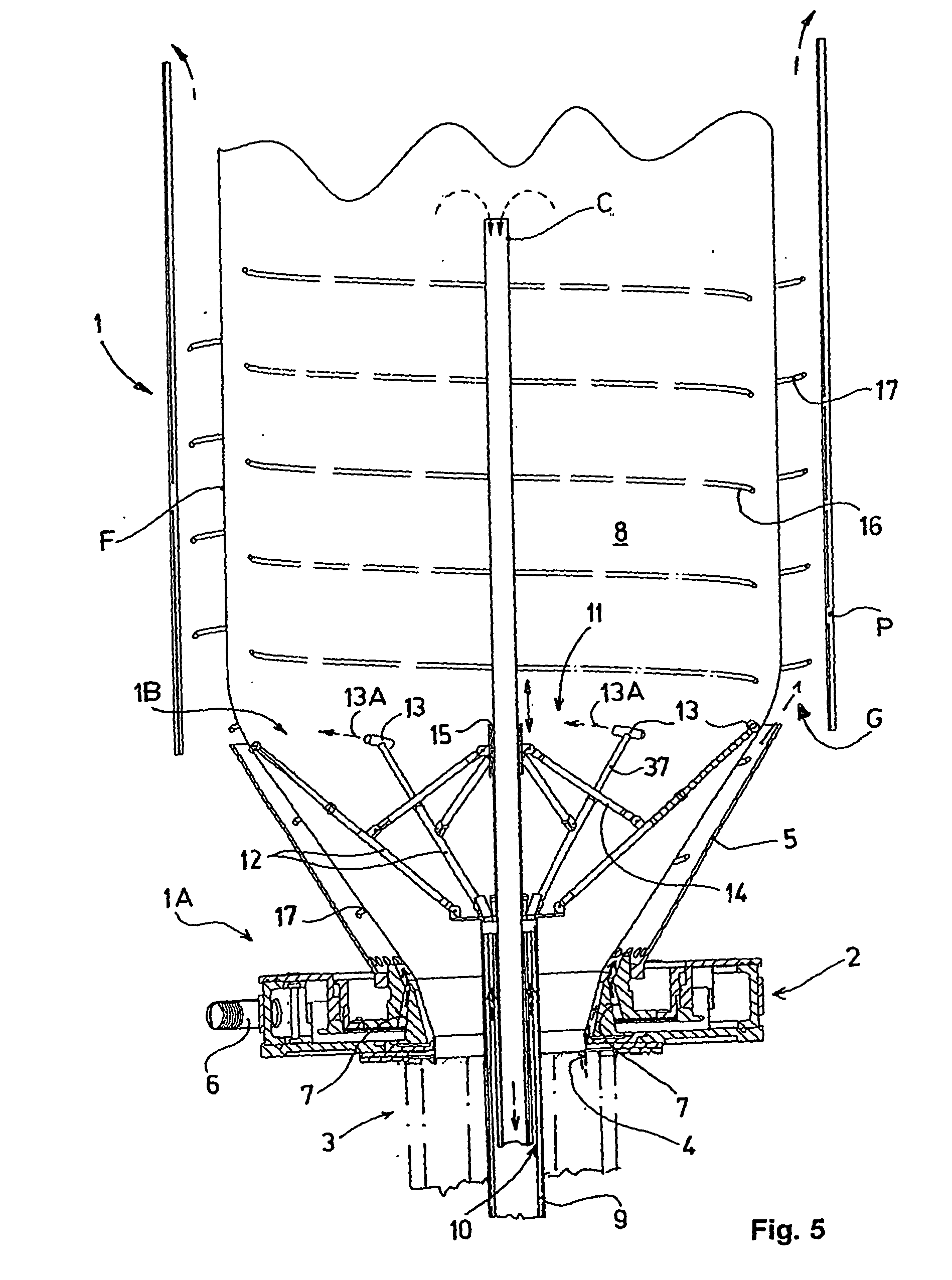
[0032] For the external air cooling, a cooling air stream of previously determined pressure is fed into a ring channel G, delimited from the inside by a cylindrical unstabilized section of the foil hose F, and by a cylindrical skirt P from outside. The coolant air is fed into the ring channel G under pressure at a bottom tangential inlet (indicated by dashed arrow). From there, the coolant air stream will flow upwards in a spiral form to an outlet at the open upper end of the ring channel G (this spiral stream is indicated by a thin dotted spiral line), and in the meantime, the foil hose F is effectively cooled ...


PUM

PropertyMeasurementUnit
temperatureaaaaaaaaaa
storage temperatureaaaaaaaaaa

Abstract

A method and apparatus for cooling extruded plastic foil hose, which is cooled down by driving a pressurized coolant along the internal and / or external skirt of the foil hose. The coolant is fed in the area of a drawing aperture tangentially to the foil hose, and the coolant thus generated is driven as a spiral stream from the tangential inlet to the outlet by a centrifugal force affecting the coolant along the internal and / or external surface of the foil hose, and by the density and pressure differences between various parts of the coolant. The apparatus includes an internal cooling unit equipped with a distribution drum provided with nozzles with tangential inlets. Its external cooling unit has a tangential inlet, which is in connection with a ring channel around the foil hose, delimited by a tubular element.

Description

BACKGROUND OF THE INVENTION [0001] The present invention relates to a method and an apparatus for cooling extruded plastic foil hoses, that is, blown tubular plastic foils. Such plastic foil hoses can be used e.g. for packaging of different products. [0002] As it is known, in the traditional way of plastic foil hose production (U.S. Pat. No. 5,607,639) a foil hose is formed from the foil material continuously exiting from a drawing aperture of an extruder nozzle, which is to be cooled rapidly after adequate extension and orientation by blowing. Cooling is usually performed by an airflow, by means of a cooling ring, which cools the external surface of the foil hose and / or a unit cooling the internal surface of the foil hose. Each of these cooling units extracts heat from the foil by heat-transfer. [0003] U.S. Pat. No. 6,068,462 discloses a device for the continuous production of blown foil hoses, which is provided with an internal and an external primary cooling unit, respectively, a...

Claims


Application Information

Patent Timeline
Patent Type & Authority Applications(United States)
IPC IPC(8): B29C55/28B29C47/20B29C48/10B29C48/32
CPCB29C47/0026B29C47/883B29C47/8835B29C2793/009B29C48/10B29C48/9125B29C48/913
Inventor PELCZ, ANTALILLES, TAMAS
Owner PELCZ ANTAL
Why Eureka
Try Eureka