Control apparatus and method for optical amplifier, optical amplifier, optical transmission apparatus, individual band gain equalizer, wavelength multiplexing transmission apparatus, optical amplifier and wavelength multiplexing transmission system using the same equalizer

a control apparatus and control method technology, applied in multiplex communication, electromagnetic repeaters, instruments, etc., can solve problems such as transmission errors, reception end becomes out of reception allowable range, and inability to amplification at one-point wavelengths

a control apparatus and control method technology, applied in multiplex communication, electromagnetic repeaters, instruments, etc., can solve problems such as transmission errors, reception end becomes out of reception allowable range, and inability to amplification at one-point wavelengths

US20060203329A1Active Publication Date: 2006-09-14FUJITSU LTD

Image

  • Control apparatus and method for optical amplifier, optical amplifier, optical transmission apparatus, individual band gain equalizer, wavelength multiplexing transmission apparatus, optical amplifier and wavelength multiplexing transmission system using the same equalizer
  • Control apparatus and method for optical amplifier, optical amplifier, optical transmission apparatus, individual band gain equalizer, wavelength multiplexing transmission apparatus, optical amplifier and wavelength multiplexing transmission system using the same equalizer
  • Control apparatus and method for optical amplifier, optical amplifier, optical transmission apparatus, individual band gain equalizer, wavelength multiplexing transmission apparatus, optical amplifier and wavelength multiplexing transmission system using the same equalizer

Examples


first embodiment

[A] Description of First Embodiment

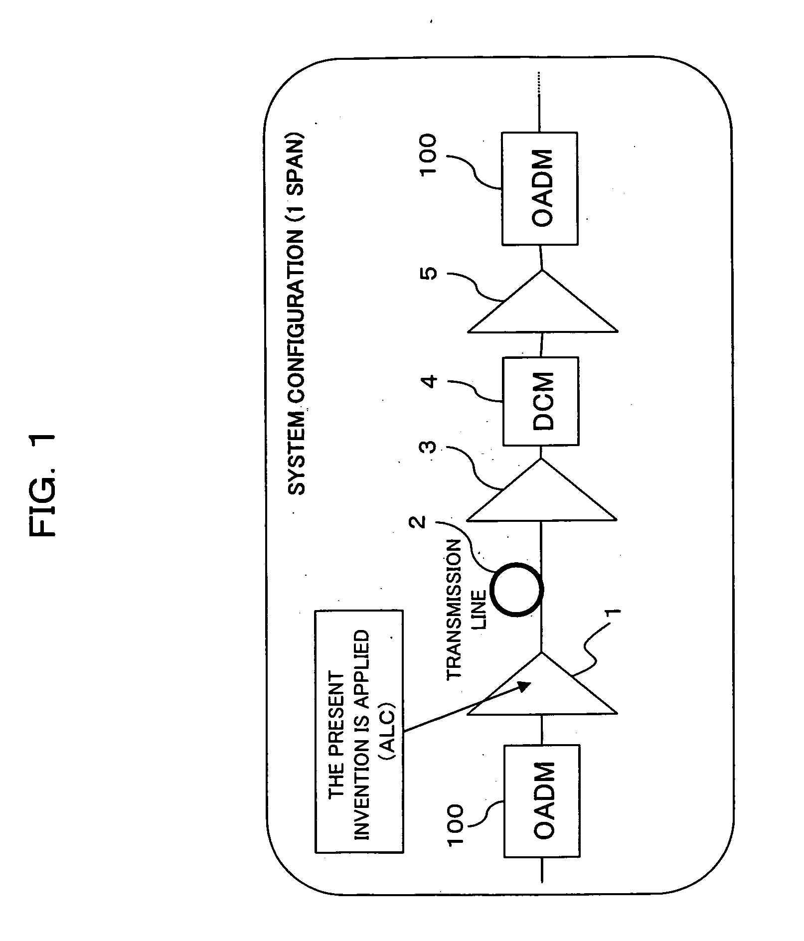
[0125]FIG. 1 is a block diagram showing a configuration of a portion of a WDM optical transmission system according to a first embodiment of the present invention. The configuration shown in FIG. 1 corresponds to one span (from one OADM node 100 to an OADM node 100 adjacent thereto) of the system described above with reference to FIG. 16, and between the OADM nodes 100, there are provided an optical amplifier (post amplifier) 1, a transmission line 2, an optical amplifier (first preamplifier) 3, a dispersion compensation module (DCM) 4 and an optical amplifier (second preamplifier) 5.

[0126] In this configuration, the post amplifier 1 is for amplifying WDM signal from the former-stage OADM node 100 up to a predetermined signal power level, and an ALC according to the present invention is applied thereto when a considerable variation in number of wavelengths occurs. Moreover, the preamplifier 3 is for amplifying WDM signal, transmitted in a state wh...

second embodiment

[B] Description of Second Embodiment

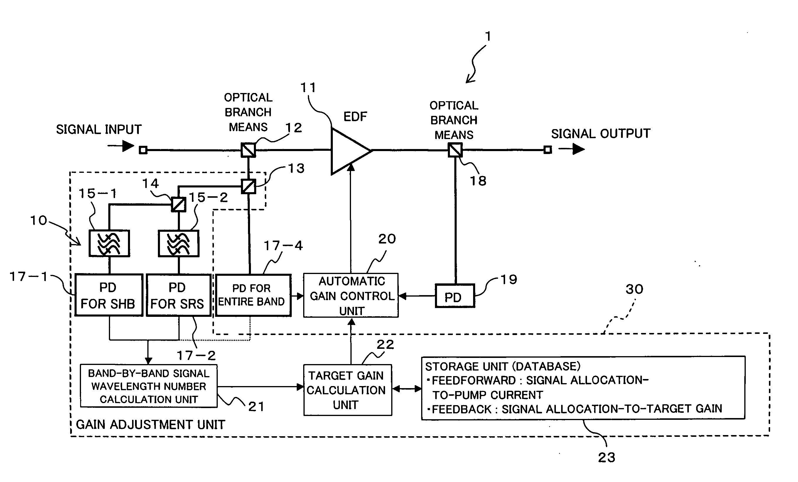
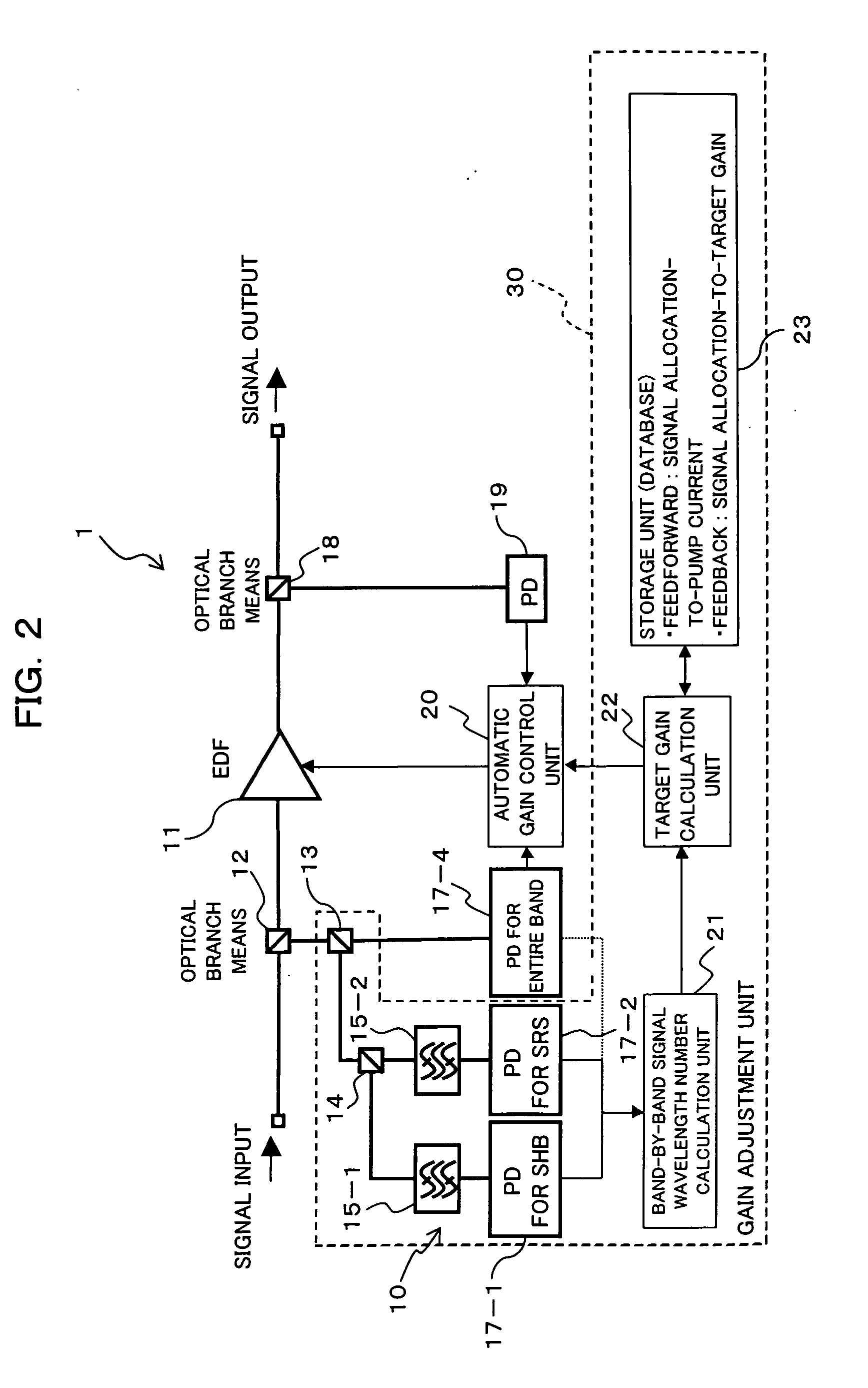
[0185] Secondly, a description will be given hereinbelow of a low-cost gain equalization device providing a high-speed response. As described above, the main factors of the variation of the wavelength flatness of signal power occurring due to the dynamic variation of the state of signal are the SHB occurring in an EDFA, the gain deviation of an EDFA and the SRS occurring in an optical transmission line. Moreover, the degree of the effect of each of the factors largely varies according to wavelength and, for example, in the case of the C band (1532 nm to 1563 nm), the effects of the SHB, the gain deviation and the SRS increases with shorter wavelength, while longer wavelength provides greater effects of the SRS and the gain deviation and an intermediate wavelength band provides a greater gain deviation effect in comparison with the other two factors.

[0186] Therefore, to suppress the variation of gain wavelength characteristic involved in the varia...


PUM

PropertyMeasurementUnit
wavelengthaaaaaaaaaa

Abstract

A control apparatus comprises a light monitoring unit for dividing a signal wavelength band into at least a band in which output light power of an optical amplifier tends to decrease at an decrease in the number of signal wavelengths and a band including a gain deviation band, and for monitoring inputted light power for the individual divided bands, a calculation unit for obtaining the number of signal wavelengths in the individual divided bands based on a monitor result, and a target gain correction unit for correcting a target gain based on a result of the calculation. This suppresses a transient variation of signal light level due to SHB or SRS at a high speed with a simple configuration without deteriorating noise characteristic, thus enabling optical amplifiers to be further disposed in a multi-stage fashion, which can lengthen the transmission distance of a transmission system including an optical add / drop unit.

Description

CROSS REFERENCE TO RELATED APPLICATIONS [0001] This application is based on and hereby claims priority to Japanese Applications No. 2005-286608 filed on Sep. 30, 2005 and No. 2005-71044 filed on Mar. 14, 2005 in Japan, each of the contents of which are hereby incorporated by reference. BACKGROUND OF THE INVENTION [0002] (1) Field of the Invention [0003] The present invention relates to a control apparatus and method for an optical amplifier, an optical amplifier, an optical transmission apparatus, an individual band gain equalizer, a wavelength multiplexing transmission apparatus, an optical amplifier and a wavelength multiplexing transmission system using the same equalizer, and more particularly to a technique suitable for use in a WDM (Wavelength Division Multiplex) optical transmission system which lengthens the transmission distance by disposing optical fiber amplifiers, represented by an Erbium-doped fiber amplifier (EDFA), in multi-stage system. [0004] (2) Description of the ...

Claims


Application Information

Patent Timeline
14 Sep 2006
Publication
US20060203329A1
IPC
H01S3/00; G02F1/35; H01S3/067; H01S3/10; H01S5/50; H04B10/07; H04B10/2507; H04B10/2537; H04B10/2543; H04B10/29; H04B10/296; H04J14/00; H04J14/02
CPC
H01S3/06754; H01S3/302; H01S3/1301; H01S3/10015; H01S3/10069; H04B10/2942; H01S3/13013; H01S3/1305
Inventors
NISHIHARA, MASATO; ONAKA, MIKI