
Apparatus, method and system of thin client blade modularity

a thin client and modular technology, applied in the direction of electrical apparatus construction details, instruments, support structure mounting, etc., can solve the problems of large organization's typical computer system becoming much more complex and therefore difficult to predict, simulate and test, and the approach could only simulate a small portion of the organization's system, and achieves easy connection and monitoring. , the effect of easy monitoring

Inactive Publication Date: 2006-09-14
CHIP PC ISRAEL
View PDF11 Cites 69 Cited by
  • Summary
  • Abstract
  • Description
  • Claims
  • Application Information

AI Technical Summary

Benefits of technology

[0019] In an embodiment of the invention, a modular chassis comprising of multiple thin-client blades removeably connectable to a common Midplane or backplane and to one or more power supplies and one or more management modules to enable multiple thin-clients operating with one or more computer networks. The invention enables building large-scale computer laboratory environments having many thin-client workstations and possibly many simulated users, easily connected and managed to simulate large computer infrastructure. Internal KVM functionality and Chaining options enables a single administrative user to easily monitor and manage large number of thin-client workstations remotely or locally through a single set of keyboard, mouse and display.
[0023] In some embodiments, the KVM module is capable of chaining with plurality of similar systems to enable centralized management of more thin-client blades than can be inserted into one of said chassis.

Problems solved by technology

In the first years of Personal Computing, each Personal Computer (PC) workstation was operated as a stand-alone system and therefore the testing of big PC deployment was typically limited to testing a single PC for functionality, stability and reliability.
The typical computer system of a large organization became much more complex and therefore much more difficult to predict, simulate, and test.
Today, large organization are faced with the challenge of designing, analyzing, and maintaining not only the individual PC workstations, but the system as whole, including the complex interaction of multiple workstations requesting data or computing resources and loading the communication networks.
This approach could only simulate small portion of the organization's system while suffering from relatively high cost.
The main disadvantages of such simulated environment are:
1 High capital investment cost in constructing the testing system due to expensive building blocks—actual PCs and the large floor space needed for the laboratory.
2 High maintenance cost due to the complex wiring needed for network and multiple channel KVMs.
In addition, the distributed management of the environment requires extensive workforce to manage and troubleshoot.
3 Lack of scalability in the workstation side—it was not practical to deploy several hundreds of PC workstations as it requires very large space, peripherals, and cabling.
4 Long setup and lack of flexibility—each setup or change may take days or weeks to build and verify due to all the cabling involved.
While this option may be much more cost efficient than the previous option, the level of fidelity achieved with such system for workstation simulation is far from the level needed for most organization.
It is difficult to predict the behavior of large distributed systems without the use of the actual hardware such as workstations.
This brings an even stronger challenge for the large organizations to ensure reliable and economical system operation.
With the thin-client trend, came also the inherent risk of centralized failures that can paralyze the organization's Information Technology (IT) system, partially or completely.
Scenarios such as security attack, virus, data-center failure, network failures and sudden loads can easily replicate and cause domino effects and therefore are extremely difficult to predict, to avoid, and to recover from.
Although there is an option to use multiple virtual (simulated) clients running on a single platform as simulated user workstation in the case of a thin-client workstation, the simulation will be even less reliable than in PC workstations as thin-clients are using completely different architectures and are difficult to simulate in current virtual machines.

Method used


Image

  • Apparatus, method and system of thin client blade modularity
  • Apparatus, method and system of thin client blade modularity
  • Apparatus, method and system of thin client blade modularity

Examples


Embodiment Construction

[0043] The following detailed description is of the best presently contemplated modes of carrying out the present invention. This description is not to be taken in a limiting sense, but is made merely for the purpose of illustrating the general principles in accordance with the present invention. The scope of the present invention is best defined by the appended claims.

[0044] The foregoing and other objects, features and advantages of the invention will become apparent from the following more particular description of exemplary embodiments of the invention, as illustrated in the accompanying drawings:

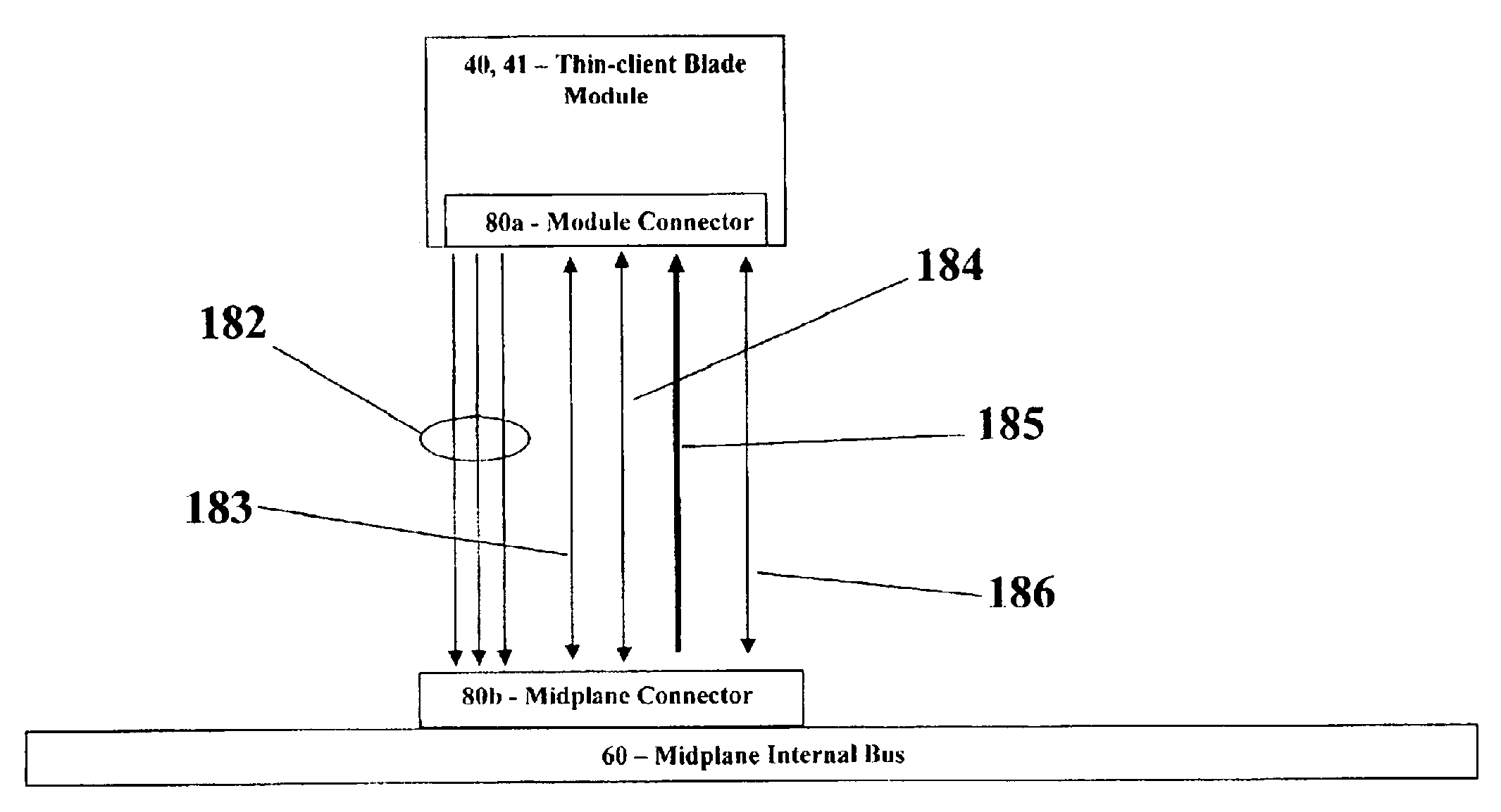
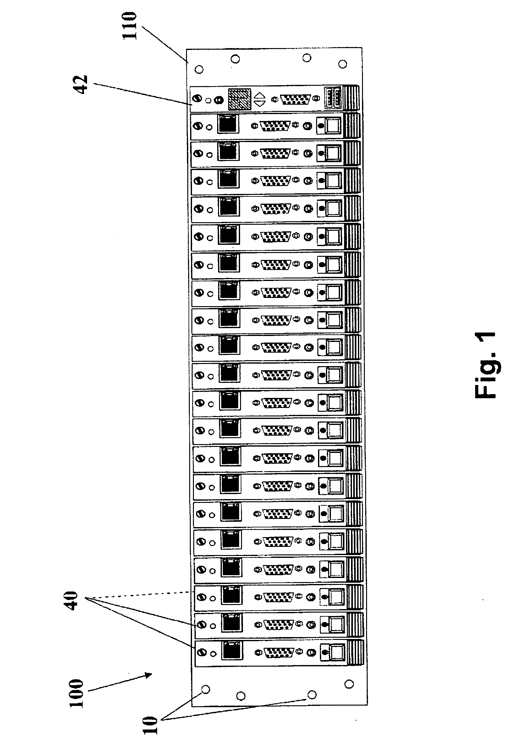
[0045] Reference is made to FIG. 1 illustrating a frontal view of an embodiment of a thin-client modular blade system 100. Chassis rack mounting holes 10 are used for securing a chassis 110 to a standard rack. Typically, standard 19″ rack geometry is being used to enable vertical buildup of multiple sets of thin-client modular blade systems 100 and network switches as needed. Chassis ...


PUM


Abstract

The present invention provides a modular chassis comprising of multiple thin-client blades removeably connectable to a common midplane and to one or more power supplies and one or more management modules to simulate multiple thin-client operating with one or more computer networks. The invention enables building large-scale computer laboratory environments having many thin-client devices and possibly many simulated users, easily connected and managed to simulate large computer infrastructure. Also disclosed in this patent is a method for performing combinations of functions including testing and simulation of normal and abnormal operational scenarios in complex server-based computing environments.

Description

FIELD OF THE INVENTION [0001] The present invention relates generally to multiple thin-clients modular system, and in particular, but not exclusively, to a thin-client blade system and architecture to enable functional and load testing of complex server based computing environments. BACKGROUND OF THE INVENTION [0002] In the first years of Personal Computing, each Personal Computer (PC) workstation was operated as a stand-alone system and therefore the testing of big PC deployment was typically limited to testing a single PC for functionality, stability and reliability. As organizations' computer systems became networked and heavily relying on centralized servers, PCs became dependent on network and server resources for their normal operation. The typical computer system of a large organization became much more complex and therefore much more difficult to predict, simulate, and test. [0003] Today, large organization are faced with the challenge of designing, analyzing, and maintainin...

Claims


Application Information

Patent Timeline
IPC IPC(8): H05K7/10
CPCH05K7/1492G06F15/16G06F17/00
Inventor AVIV, SOFFER
Owner CHIP PC ISRAEL
Features
  • Generate Ideas
  • Intellectual Property
  • Life Sciences
  • Materials
  • Tech Scout
  • Unparalleled Data Quality
  • Higher Quality Content
  • 60% Fewer Hallucinations
Learn More