Method and device for impulse response measurement

Inactive Publication Date: 2006-09-14
NOKIA CORP
View PDF12 Cites 29 Cited by
  • Summary
  • Abstract
  • Description
  • Claims
  • Application Information

AI Technical Summary

Benefits of technology

[0046] One advantage of the invention is that only one searcher can be used for impulse measurement. Let us assume the following example. The common pilot channel has a spreading factor of 256, the over sampling ratio is Ns, the IRM is done over 256 chips, there are L fingers in the Rake receiver and M receiving antennas forming the diversity antenna. According to the prior art solution (EP 396101), where both antennas have their own searcher, M*Ns*256 matched filter operations are required in order to detect the delays and the corresponding correlation values of all antennas. If one searcher is excluded in the example as in the present invention, the required operations diminish to Ns*256 matched filter operations per measurement. Moreover, if the reduced IRM is performed for the other antenna(s), Ld*(M−1) additional matched filter operations, where Ld is the number of delays found by the full IRM measurement, are needed. Typically, Ld <<Ns*256 and often smaller than L. Therefore, the total computational complexity of M*Ns*256+Ld*(M−1) operations is less complex in the present invention compared to the prior art implementation (EP 396101).
[0047] According to the prior art solution U.S. Pat. No. 6,628,733, the impulse responses of each antenna can be measured consecutively. Therefore, there is no need for additional hardware. One of the drawbacks of this prior art solution is that the power consumption is still the same as in the previously described prior art solution. Moreover, the method presented in U.S. Pat. No. 6,628,733 requires more memory, because the (full) impulse responses of both antennas are

Problems solved by technology

When the (W)CDMA system is considered, the interference consists of other cell interference, own cell interference from other users of the same cell and external interference from another systems.
This method therefore includes some inherent delay.
Furthermore one drawback in this method is that any errors in symbol decisions affect the final channel estimate.
This method has a relatively long convergence time.
Some error factors affect the impulse response measurement, which are due to timing estimate inaccuracy, frequency offsets between transmitter's and receiver's clocks or relative velocity between the mobile station and the base station.
At present a problem is to find delays of the radio channel for (W)CDMA terminal that comprises a receiver, which supports antenna diversity reception.
The drawback is a high amount of searchers resulting in high computational complexity and leading t

Method used


Image

  • Method and device for impulse response measurement
  • Method and device for impulse response measurement
  • Method and device for impulse response measurement

Examples


Example

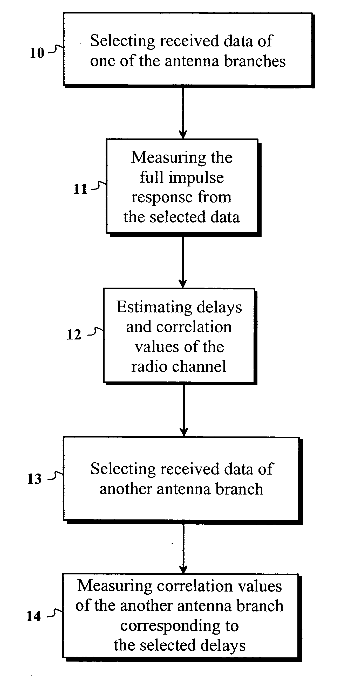
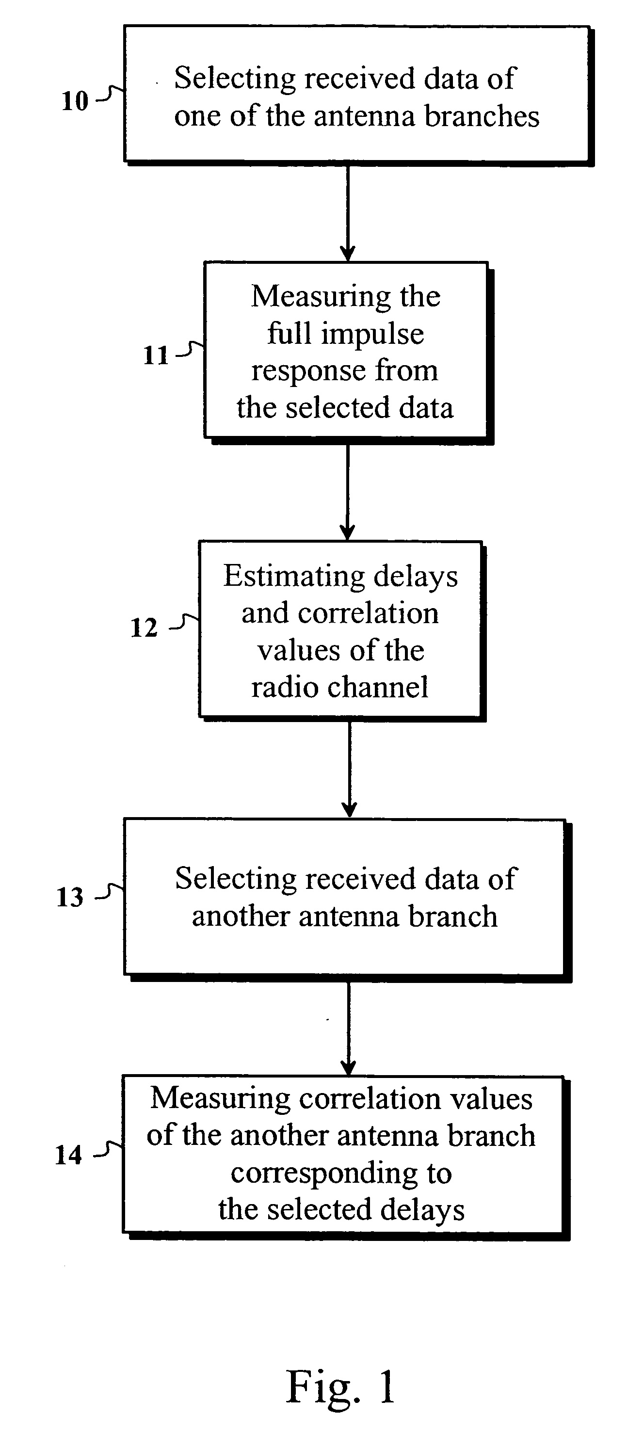
[0067] Reference will now be made in detail to the embodiments of the present invention, examples of which are illustrated in the accompanying drawings. The invention discloses a simple way to measure impulse responses of a radio channel in a receiver having a diversity antenna array. Especially, the purpose of the invention is to reduce the effects of the problems existing in prior art. The problems in the prior art solutions are greater computational complexity, which leads to the greater amount of hardware, power consumption and / or delays between measurements of each receive antenna. By measuring the impulse response cost-efficiently it is possible to fight effectively against the multipath propagation with a CDMA or WCDMA mobile terminal using e.g. a rake receiver.

[0068] One embodiment of the method according to the invention is disclosed in FIG. 1. This embodiment discloses a straightforward finger allocation procedure for one antenna branch. The idea of the invention is to se...


PUM


Abstract

The invention discloses a method, a receiver and a wireless terminal for measuring an impulse response e.g. in a (W)CDMA terminal having at least two receiving antenna branches with diversity reception. In the method one antenna branch is selected, e.g. by choosing the antenna with a good signal to interference ratio. An impulse response is measured for the selected antenna branch (full IRM) with a searcher. The delays of the propagation paths of the radio channel are estimated by selecting the delay values, whose correlation value exceed a threshold value. The impulse response measurement for the other antenna branch is performed only on the selected delay values (reduced IRM) with the searcher. The finger allocation for the selected antenna branch can be done immediately after the full IRM and for the other antenna immediately after the reduced IRM. The finger allocation for all branches can alternatively take place after the reduced IRM, simultaneously. The invention may be implemented in at least one of a programmable device, dedicated hardware, programmable logic and any other processing device.

Description

FIELD OF THE INVENTION [0001] The invention relates to the impulse response measurement (IRM) in a receiver using Code Division Multiple Access (CDMA) or Wideband Code Division Multiple Access (WCDMA) technology. BACKGROUND OF THE INVENTION [0002] One common phenomenon in mobile or radio communication technology is the multipath propagation. In the multipath propagation a radio signal propagates from a transmitter through-different propagation paths until it reaches a receiver. The radio signal can reflect from different surfaces such as building walls and other objects of nature. Different propagation paths have different lengths, which means that the transmitted signal is received multiple times at different time instants in the receiver. The signal is also attenuated and its phase is rotated differently in different propagation paths. The transmitter in mobile communication may be a fixed base station and the receiver may be a mobile phone. This leads to the fact that the propert...

Claims


Application Information

Patent Timeline
IPC IPC(8): H04B1/707H04L1/02
CPCH04B1/7093H04B1/7113H04B1/7117H04B7/0897H04L1/02
Inventor VENTOLA, MIKA
Owner NOKIA CORP
Why Eureka
Try Eureka