Diffractive optical element and bidirectional optical communication module using the same

a technology of optical communication module and optical element, applied in the direction of optics, instruments, optical light guides, etc., can solve the problems of reducing module performance and poor signal receiving accuracy, and achieve the effect of increasing diffraction efficiency, reducing the size of the optical communication module, and high module performan

Inactive Publication Date: 2006-09-14
KONICA MINOLTA INC
View PDF3 Cites 2 Cited by
  • Summary
  • Abstract
  • Description
  • Claims
  • Application Information

AI Technical Summary

Benefits of technology

[0021] According to the diffractive optical element of the present invention, the diffraction angle can be maintained and the diffraction efficiency can be increased. Further, according to the optical communication module of the present invention, high module performance can be realized, and the downsizing of the optical communication module and the improvement of the light receiving performance can be realized.
[0022] The invention itself, together with further objects and attendant advantages, will best be understood by reference to the following detailed description taken in conjunction with the accompanying drawings.

Problems solved by technology

Accordingly, because the receiving signal is detected on the light receiving surface of the light receiving element by using the +1-order diffracted light beam 108 (or −1-order diffracted light beam 109) whose light amount is small, the signal receiving accuracy by the receiving signal becomes poor, therefore, the module performance is lowered.

Method used


Image

  • Diffractive optical element and bidirectional optical communication module using the same
  • Diffractive optical element and bidirectional optical communication module using the same
  • Diffractive optical element and bidirectional optical communication module using the same

Examples


first embodiment

The First Embodiment

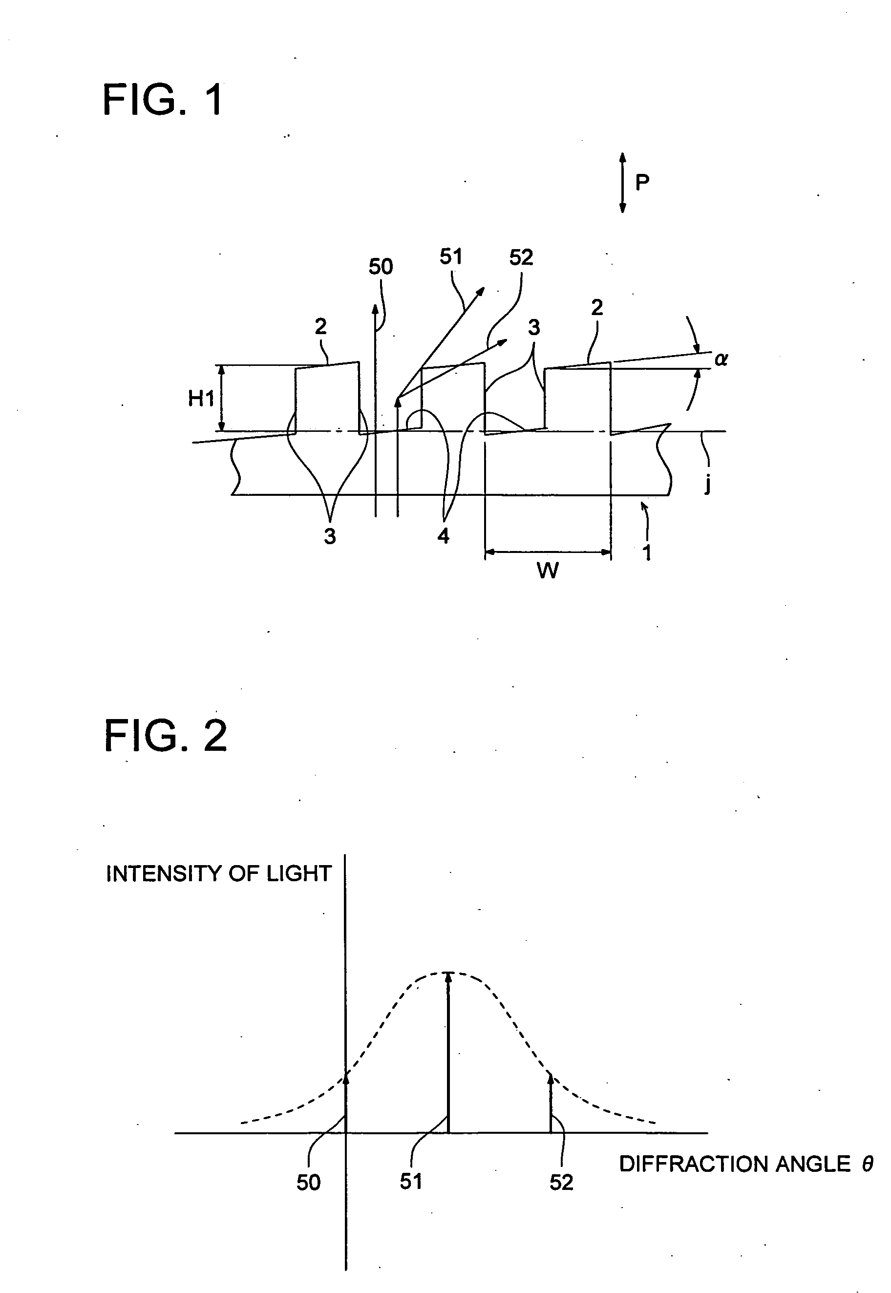
[0035]FIG. 1 is a partial side view showing main parts of the diffractive optical element according to the first embodiment. FIG. 2 is a view generally showing the intensity of light of each of the 0-order diffracted light beam, +1-order diffracted light beam, and +2-order diffracted light beam.

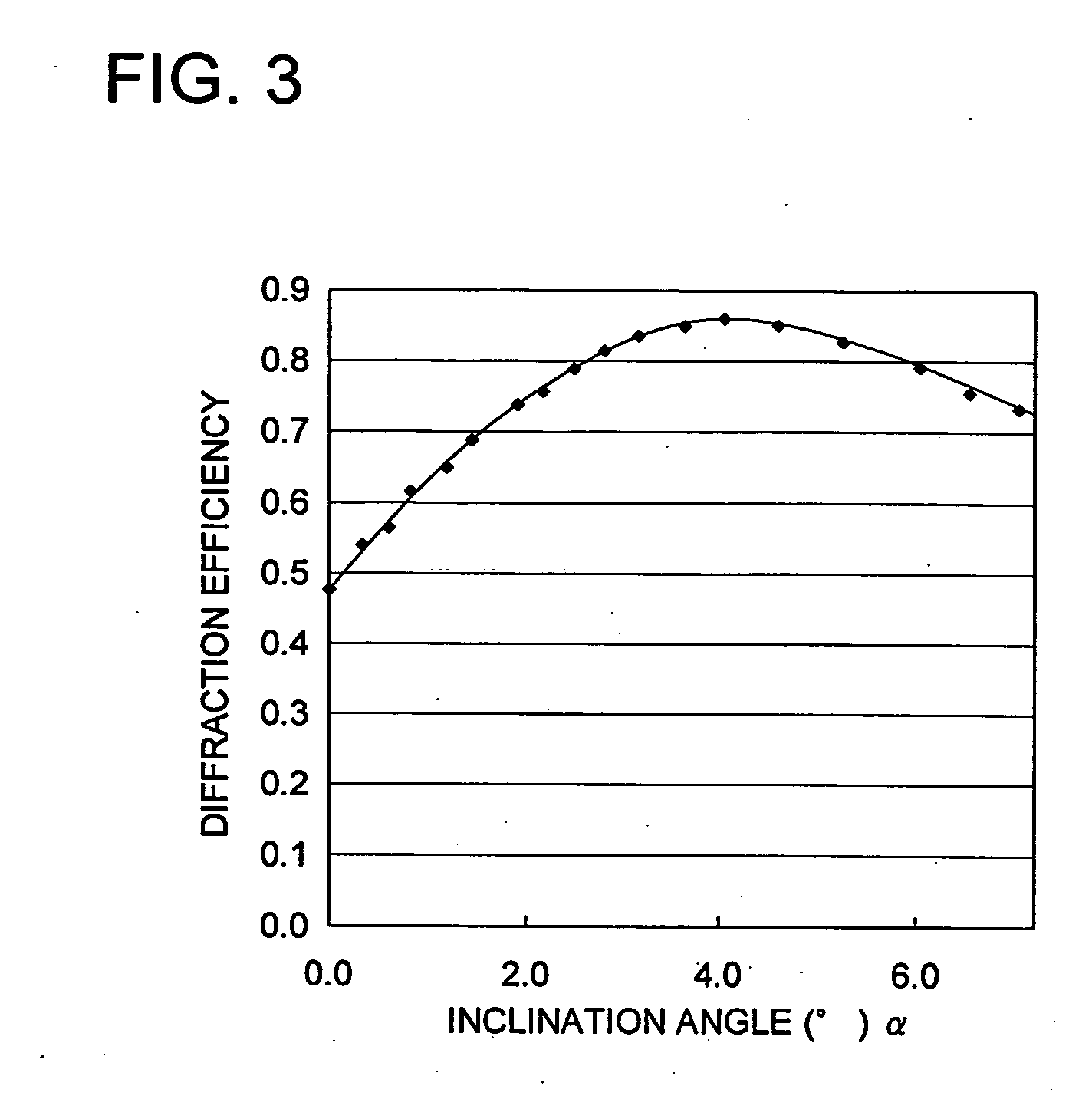
[0036] As shown in FIG. 1, the diffractive optical element according to the first embodiment is composed of the diffraction grating of the concave and convex shape by which different wavelengths are demultiplexed. The diffraction grating is formed into a shape whose same shape in which the diffraction surface top part 2 on the convex side and the diffraction surface bottom part 4 on the concave side repeat through the rising surface part 3 along the optical axis direction P is continued. That is, the diffraction grating is formed into a structure of the binary shape of so-called 2-level. The diffractive optical element 1 is composed of the optical material such as the gla...

second embodiment

The Second Embodiment

[0047]FIG. 4 is a partial side view showing main parts of the diffractive optical element according to the second embodiment. FIG. 5 is a partial side view showing main parts of another diffractive optical element according to the second embodiment.

[0048] As shown in FIG. 4 and FIG. 5, the diffractive optical elements 5, 5′ according to the second embodiment are reflection type in which the incident light beam is reflected, and is structured by the concave and convex shape diffraction grating by which the different wavelengths are demultiplexed, and the diffraction grating is formed into the same shape in which the diffraction surface top part 6 on the convex side and the diffraction surface bottom part 8 are repeated through the rising surface part 7 along the optical axis direction P. The diffraction surface grating side is formed into a reflection surface 9 formed of the high reflective surface onto which, for example, metals such as Ag, Al, Au, are evaporat...

third embodiment

The Third Embodiment

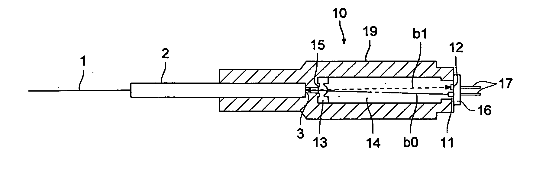
[0056]FIG. 6(a) is a main part sectional view in the longitudinal direction of the optical communication module according to the third embodiment. FIG. 6(b) is an enlarged plan view showing the diffraction grating formed on the surface of a combination lens 13 in FIG. 6(a). FIG. 6(c) is a schematic sectional view in which the diffraction grating formed on the surface of a combination lens 13 is cut in C-C direction in FIG. 6(b), and its section is enlarged.

[0057] As shown in FIG. 6(a), the bidirectional optical communication module 10 is provided with: in a long and narrow almost cylindrical casing 10, the light emitting element 11; the light receiving element 12; and the combination lens 13 as the optical device. The light emitting element 11 and the light receiving element 12 are provided common substrate 16, and fixed to the casing together with the substrate 16. Further, a plurality of connection pins protruded outside from the substrate 16 are electrically ...


PUM


Abstract

A diffractive optical element 1 has a diffraction grating which multiplexes the light beam of the different wavelength, and the diffraction grating is structured by a binary structure in which the diffraction surface top part 2 and the diffraction surface bottom part 4 repeat the concave and convex shape through a rising surface 3 part along the optical axis direction P, and the diffraction surface top part and the diffraction surface bottom part are inclined to the rising surface part. By this diffractive optical element 1, the diffraction angle of the light beam is maintained, and the diffraction efficiency of the light beam can be improved. Then, by using this diffractive optical element 1, the optical communication module in which, while the separation angle of the light beam of the different wavelength is maintained, the signal receiving performance is increased, can be provided.

Description

BACKGROUND OF THE INVENTION [0001] 1. Field of the Invention [0002] The present invention relates to a diffractive optical element having the diffraction grating of the concave and convex shape and an optical communication module using this diffractive optical element. [0003] 2. Description of the Related Art [0004] In an optical communication system by an optical transmission path such as an optical fiber, a plurality of optical signals whose wavelengths are different by WDM (Wavelength Division Multiplexing) are simultaneously transmitted by the optical fiber, and for the signal sending receiving terminal, a bidirectional optical transmission module is used. In such a bidirectional optical transmission module, for the purpose that the light beam for signal sending (ascent light beam) from the light emitting element toward the terminal of the optical fiber, and the light beam for signal receiving (decent light beam) from the terminal of the optical fiber toward the light receiving ...

Claims


Application Information

Patent Timeline
Patent Type & Authority Applications(United States)
IPC IPC(8): G02B6/36
CPCG02B5/1866G02B6/29311G02B6/4206G02B6/4246
Inventor OZEKI, YUKIHIRO
Owner KONICA MINOLTA INC
Why Eureka
Try Eureka