Method of making a composite membrane

Active Publication Date: 2006-09-14
MT ACQUISITION HLDG LLC +1
View PDF18 Cites 13 Cited by
  • Summary
  • Abstract
  • Description
  • Claims
  • Application Information

AI Technical Summary

Problems solved by technology

Therefore, most materials are difficult to chemically or mechanically attach or connect to ePTFE.
Such a membrane can suffer from development of “pin holes” when ion exchange material separates from the surfaces defining the pores in the membrane.
Pin holes have a detrimental effect on the performance of the composite membrane.

Method used


Image

  • Method of making a composite membrane
  • Method of making a composite membrane
  • Method of making a composite membrane

Examples


Embodiment Construction

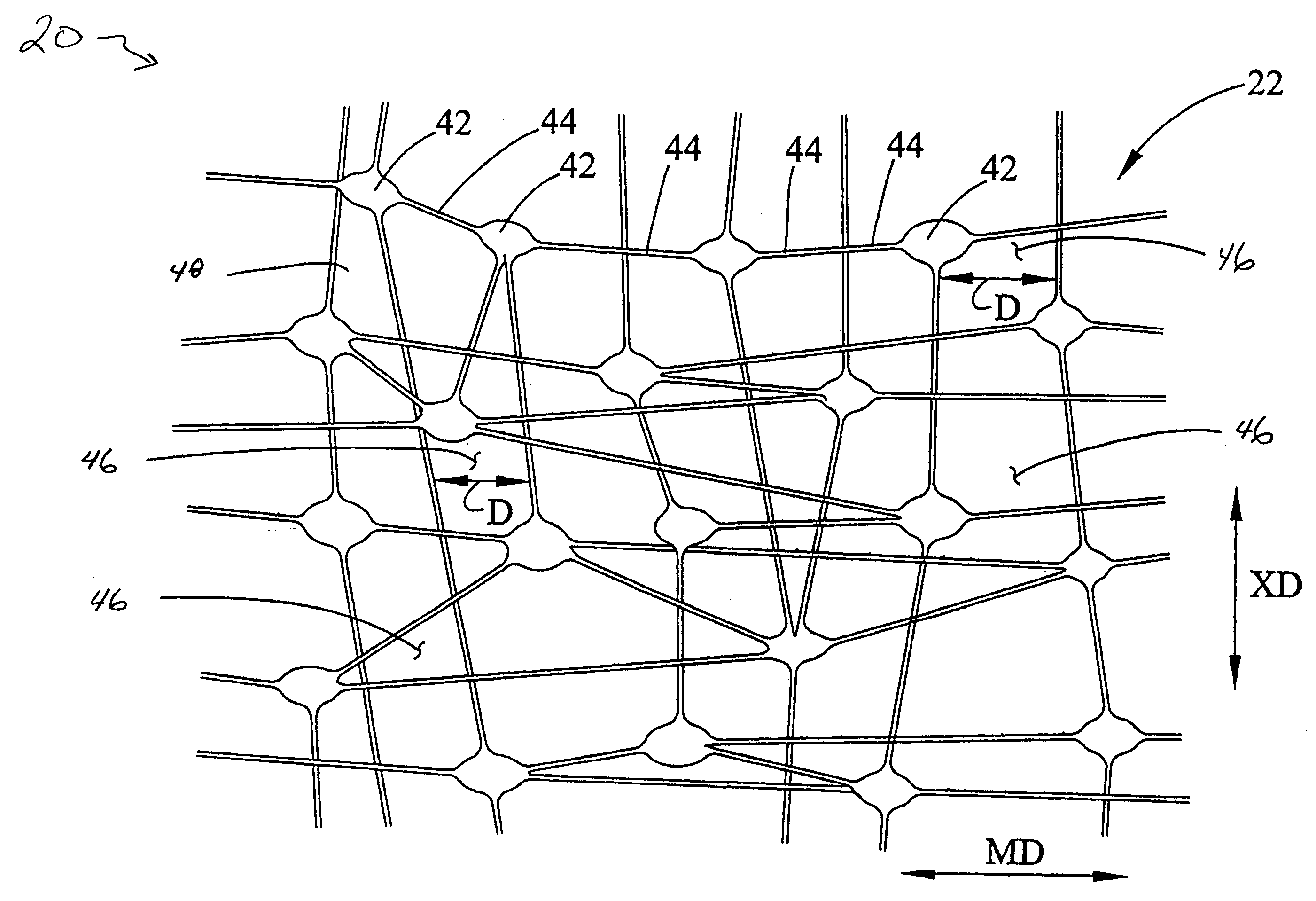
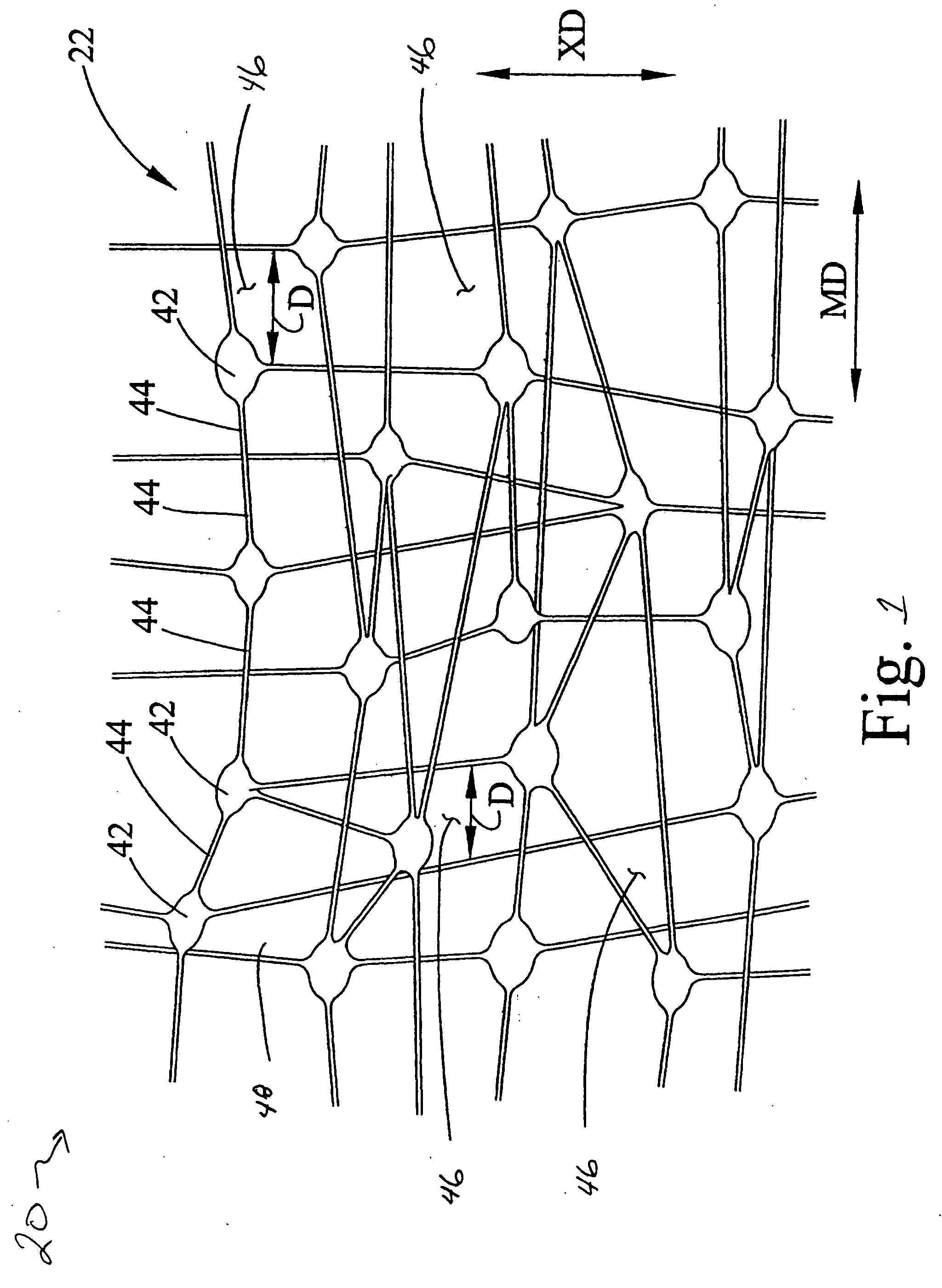
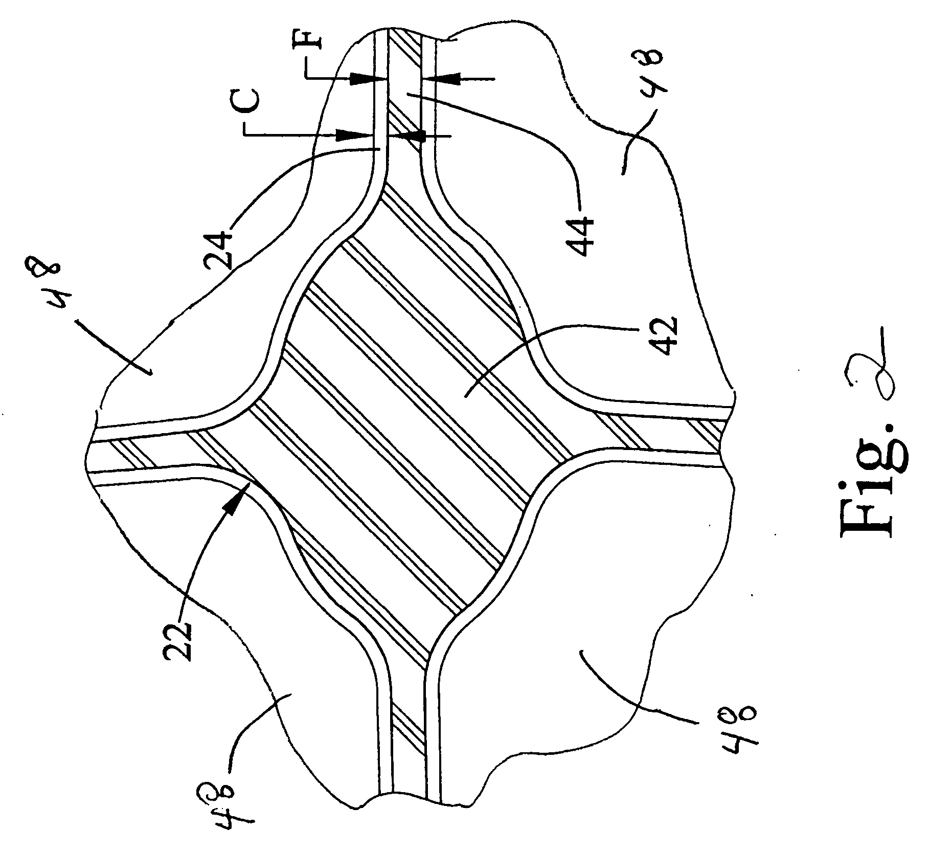
[0015] A composite membrane and a method of making the composite membrane are discussed in detail below. The composite membrane can be used in filter apparatus or can be used, with the addition of an ion exchange, as a proton exchange membrane material in a fuel cell. The composite membrane includes, in an exemplary embodiment, a porous base membrane having a plurality of pores and a coating applied to the base membrane using a densified gas, for example, a supercritical fluid or a near critical fluid, as a solvent. The coating is deposited onto the base membrane without blocking the pores of the membrane by changing the conditions of the supercritical fluid, for example, temperature and / or pressure. An ion exchange material can then be applied to the coated surface of the membrane. The coating used is selected to be compatible with the material of the base membrane. By compatible it is meant that the coating material will “wet-out” the surface of the base membrane to form a continu...


PUM

PropertyMeasurementUnit
Fractionaaaaaaaaaa
Fractionaaaaaaaaaa
Thicknessaaaaaaaaaa

Abstract

A method of making a composite membrane with ion exchange properties includes, in an exemplary embodiment, forming a porous membrane from a first material, dissolving a coating material in a fluid at supercritical conditions, and exposing the porous membrane to the coating material dissolved in the supercritical fluid. The method also includes precipitating a uniform coating of the coating material onto an exterior surface of the porous membrane by changing the supercritical conditions of the fluid to a non-supercritical condition, and applying an ion exchange material to the coated porous membrane so that the ion exchange material is in intimate contact with substantially all of the coated surfaces of the porous membrane.

Description

BACKGROUND OF THE INVENTION [0001] This invention relates generally to composite porous membranes, and more particularly to, composite porous membranes compatible with ion exchange materials. [0002] It is known that a porous membrane may have at least one property that is limited by the material from which the membrane is made. For example, a porous membrane made from expanded polytetrafluoroethylene (ePTFE) material has excellent hydrophobic properties, has low surface energy, and is extremely inert. Therefore, most materials are difficult to chemically or mechanically attach or connect to ePTFE. [0003] U.S. Pat. No. 5,976,380 discloses a hydrophilic coating on a surface of a porous polytetrafluoroethylene (PTFE) membrane by wetting the membrane with the solution, applying the solution under pressure or pre-wetting the membrane with a wetting agent such as methanol, ethanol, isopropanal or acetone. U.S. Pat. Nos. 6,228,447; 6,410,084 6,676,993, and 6,854,603 disclose an improved me...

Claims


Application Information

Patent Timeline
IPC IPC(8): B05D7/00B05D5/12
CPCB01D67/0088B01D71/36B01D2311/2623B01D2323/28B01D2323/42B01D2325/12B01D2325/14B01D2325/16H01B1/122H01M8/1023H01M8/1025H01M8/1027H01M8/1032H01M8/1039H01M8/1053H01M8/106H01M2300/0082Y02E60/521B01D2323/225Y02E60/50Y02P70/50
Inventor KLARE, ROBERT J.DEYOUNG, JAMESMCCLAIN, JAMES B.
Owner MT ACQUISITION HLDG LLC
Why Eureka
Try Eureka