Structure and method of thermal stress compensation

a technology of thermal stress compensation and structure, applied in the direction of heat measurement, instruments, transportation and packaging, etc., can solve the problems of voids or cracks on the surface of the film, overall appearance of the film and substrate will become warped, and the effect of reducing the stress accumulated

Inactive Publication Date: 2006-09-14
NAT CENT UNIV
View PDF4 Cites 45 Cited by
  • Summary
  • Abstract
  • Description
  • Claims
  • Application Information

AI Technical Summary

Benefits of technology

[0012] In view of the above, an object of the present invention is to provide a structure and a method of thermal stress compensation, wherein a film for compensation is formed on the substrate, so as to reduce the stress accumulated between the film deposited on the substrate and the substrate.

Problems solved by technology

Therefore, the method of reducing the stress through the control is valuable in the MEMS and precise optical elements, and becomes an important issue to research and develop.
Once there is too much stress accumulated on the film, the film will release a portion of the stress in the form of surface defect and deformation, and accordingly the overall appearance of the film and substrate will become warped.
However, when the tensile stress is too large, voids or cracks will occur on the surface of the film 10.
However, when the compressive stress is too large, hillocks will occur on the surface of the film 10.
When the situation goes severely, cracks or bumps will be generated on the film disposed on the substrate, resulting in variation of the optical or electrical properties of the film devices.

Method used


Image

  • Structure and method of thermal stress compensation
  • Structure and method of thermal stress compensation
  • Structure and method of thermal stress compensation

Examples


embodiment 1

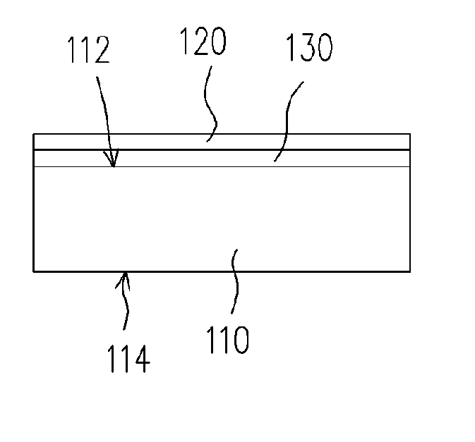
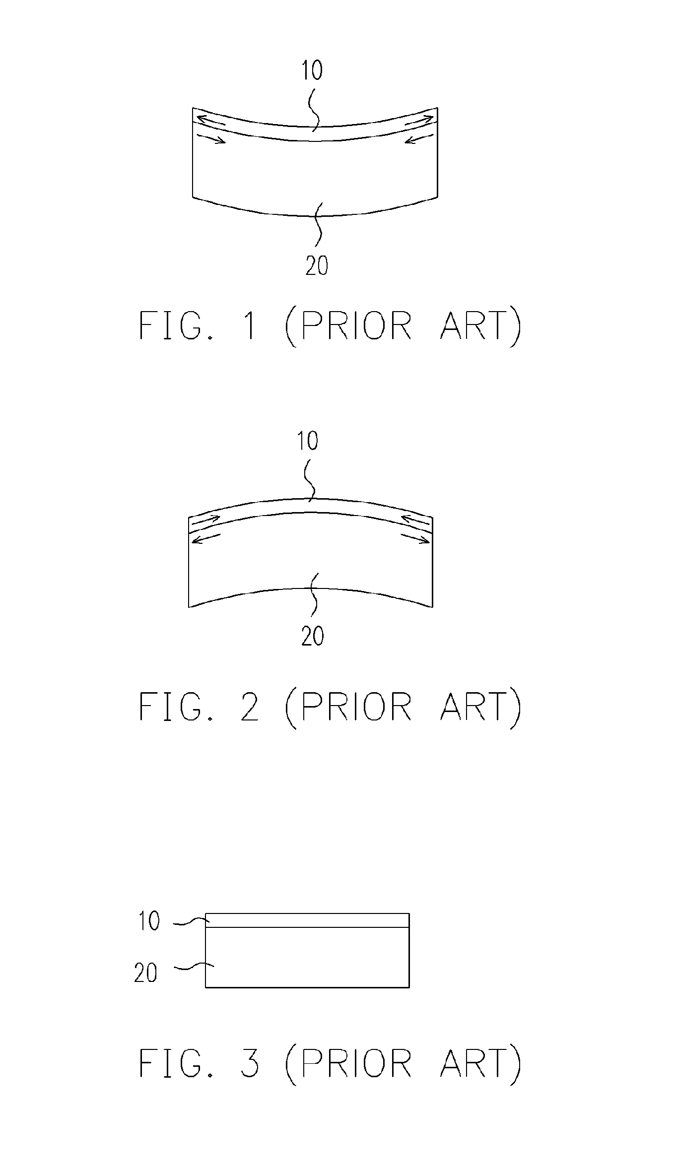
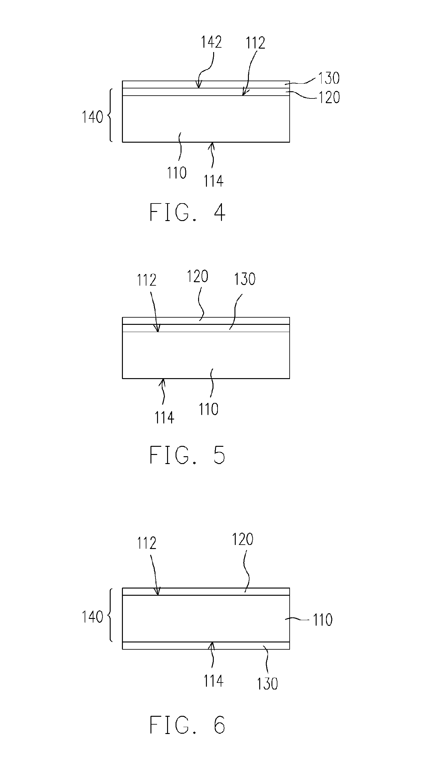
[0028] Referring to FIG. 4, it depicts the schematic view of a film used for stress compensation according to the first preferred embodiment of the present invention. A substrate 110 has a first surface 112, and a corresponding second surface 114. It is known that a film 120 is intended to be formed on the first surface 112 of the substrate 110. Provided that the coefficients of thermal expansion are, for example, 8×10⁻⁶ / ° C. and 6×10⁻⁶ / ° C., after the manufacture process of the film at high temperature is finished, and the temperature drops back to the room temperature (25° C.), the substrate 110 may endure a compressive stress, for example −1.62 Gpa, and the film 120 may endure a tensile stress. At this time, the substrate 110 and the film 120 may form a warping structure 140, as shown in FIG. 1.

[0029] Under this situation, in order to compensate the warping condition of this warping structure 140, a film 130 having a negative coefficient of thermal expansion is additionally form...

embodiment 2

[0033] Referring to FIG. 7, it depicts the schematic view of a film used for stress compensation according to a second preferred embodiment of the present invention. It is known that the stress endured by the substrate 210 at the working temperature of 100° C. is intended to be maintained at zero. Provided that the coefficient of thermal expansion of the substrate 210 is for example 7.5×10⁻⁶ / ° C., the substrate 210 appears to be under tensile stress at the working temperature, due to the stress of the film 220 formed on the substrate 210. Wherein, the value of tensile stress is for example 0.42 Gpa. And the film 220 may endure the compressive stress. At this time, the substrate 210 and the film 220 may form a warping structure 240, as shown in FIG. 2.

[0034] Under this situation, in order to compensate the warping condition of the warping structure 240, a film 230 having a negative coefficient of thermal expansion is additionally formed on the convex surface 242 of the warping struc...

embodiment 3

[0038] Referring to FIG. 10, it depicts the schematic view of the film used for compensation according to a third preferred embodiment of the present invention. The substrate 310 has a first surface 312, and a corresponding second surface 314. It is known that the film 320 is intended to be formed on the first surface 312 of the substrate 310. Provided that the coefficient of thermal expansion of the substrate 310 is for example 8.5×10⁻⁶ / ° C., and the coefficient of thermal expansion of the film 320 is for example 7.75×10⁻⁶ / ° C. the substrate 310 and the film 320 would form a warping structure 340 as shown in FIG. 2, when the temperature drops back to the room temperature (25° C.) after the manufacture process of the film at high temperature is finished.

[0039] Under this situation, in order to compensate the warping condition of this warping structure 340, a film 330 having a negative coefficient of thermal expansion is additionally formed on the concave surface of the warping stru...


PUM

PropertyMeasurementUnit
temperatureaaaaaaaaaa

Abstract

A structure of thermal stress compensation at least comprises a substrate, a first film and a second film. The substrate has a first positive coefficient of thermal expansion. The first film having a second positive coefficient of thermal expansion is over the substrate. The second film having a third negative coefficient of thermal expansion is over the substrate.

Description

CROSS-REFERENCE TO RELATED APPLICATION [0001] This application claims the priority benefit of Taiwan application serial no. 94107086, filed on Mar. 9, 2005. All disclosure of the Taiwan application is incorporated herein by reference. BACKGROUND OF THE INVENTION [0002] 1. Field of Invention [0003] The present invention relates to a structure and a method of thermal stress compensation, and more particularly to a structure and a method of thermal stress compensation utilizing films to compensate the stress distribution on a substrate. [0004] 2. Description of Related Art [0005] As the development of the manufacture process of microelectromechanical system (MEMS) and the epitaxy technique, the microelement and film manufacturing techniques grow in widespread applications. The electrical and optical performances of the elements are significantly influenced by interfaces of the related film structure, wherein the stress effects between each structural layer is a dominant research issue,...

Claims


Application Information

Patent Timeline
Patent Type & Authority Applications(United States)
IPC IPC(8): H01L29/12G01K5/68B21D39/00
CPCB81B3/0072B81C2201/0167C23C14/06C23C16/30Y10T428/12528G01K5/68Y10T428/125Y10T428/12535Y10T428/12493G01K5/62
Inventor CHEN, JYH-CHENSHEU, GWO-JIUN
Owner NAT CENT UNIV
Why Eureka
Try Eureka