Methods of manufacturing a crystal-oriented ceramic and of manufacturing a ceramic laminate

a technology of crystal-oriented ceramics and manufacturing methods, which is applied in the direction of semiconductor/solid-state device manufacturing, basic electric elements, electric apparatus, etc., can solve the problems of unobtainable piezoelectric properties, difficulty in uniform dispersibility, and inability to uniformly disperse seed crystals, etc., to achieve excellent orientation degree, shorten the calcining time, and improve the effect of calcination efficiency

Inactive Publication Date: 2006-09-14
DENSO CORP
View PDF7 Cites 7 Cited by
  • Summary
  • Abstract
  • Description
  • Claims
  • Application Information

AI Technical Summary

Benefits of technology

[0029] As a result, the ceramic laminate can be manufactured, wherein the crystal-oriented ceramic layers in which a crystal plane of each of the crystal grains constituting the polycrystalline substance is oriented, and the internal electrode layers are alternately stacked. The ceramic laminate can exert a high power, since it has the crystal-oriented ceramic layer with an excellent orientation degree. Thus, the ceramic laminate can be suitably utilized, for example, in an injector for injecting fuel in an automobile.
[0030] Further, in the method for manufacturing a ceramic laminate of the second present invention, as in the case of the above first invention, it is possible to make a calcining time of the calcining step shorter than in a method with conventional templates. It also is possible to omit a step of making templates. Therefore, the ceramic laminate can be made in a shorter time, and at low cost.

Problems solved by technology

However, as shown in the same Figure, in a method of manufacturing a crystal-oriented ceramic using templates, when the green sheet 9 is prepared, it is difficult to uniformly disperse seed crystals 95, which are templates, in the slurry of a piezoelectric material, and there has been a potential for non-uniformity to occur in a dispersing state of the seed crystals 95 within the green sheet 9.
Therefore, in the crystal-oriented ceramics obtained after calcining, non-uniformity of piezoelectric properties occurred, thus there has been a potential for desired piezoelectric properties to be unobtainable.
As a result, there has been a problem that crystal-oriented ceramics could not offer a sufficient power, even in a case of applying them to piezoelectric ceramics of the laminate-type piezoelectric element.
As shrinkage factors of the piezoelectric material and the templates are different at the time of calcining, there has been a problem of easily causing micro spaces and internal stresses.
Further, in a conventional method of manufacturing the crystal-oriented ceramics using templates, there have been problems of taking a long time for calcining and increasing a manufacturing cost.

Method used


Image

  • Methods of manufacturing a crystal-oriented ceramic and of manufacturing a ceramic laminate
  • Methods of manufacturing a crystal-oriented ceramic and of manufacturing a ceramic laminate
  • Methods of manufacturing a crystal-oriented ceramic and of manufacturing a ceramic laminate

Examples


example 1

[0119] Next, an example according to the present invention is further explained using FIGS. 1-7.

[0120] In this Example, crystal-oriented ceramics are manufactured, which are composed of a polycrystalline substance comprising a perovskite structure (ABO3) as the main component, and in which a crystal plane of each of the crystal grains constituting the polycrystalline substance is oriented.

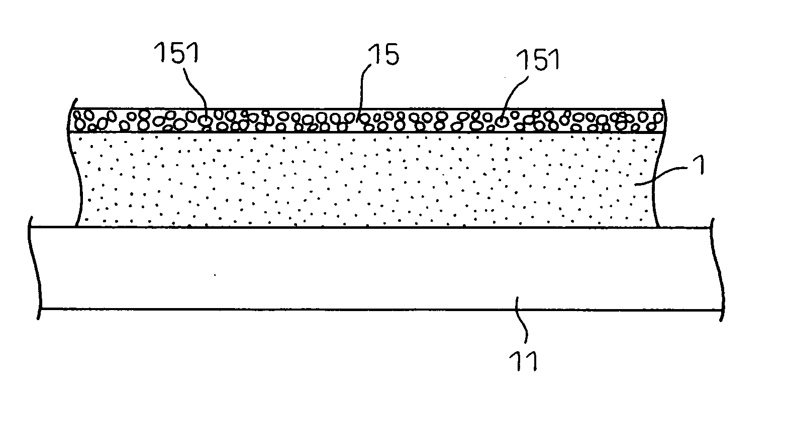
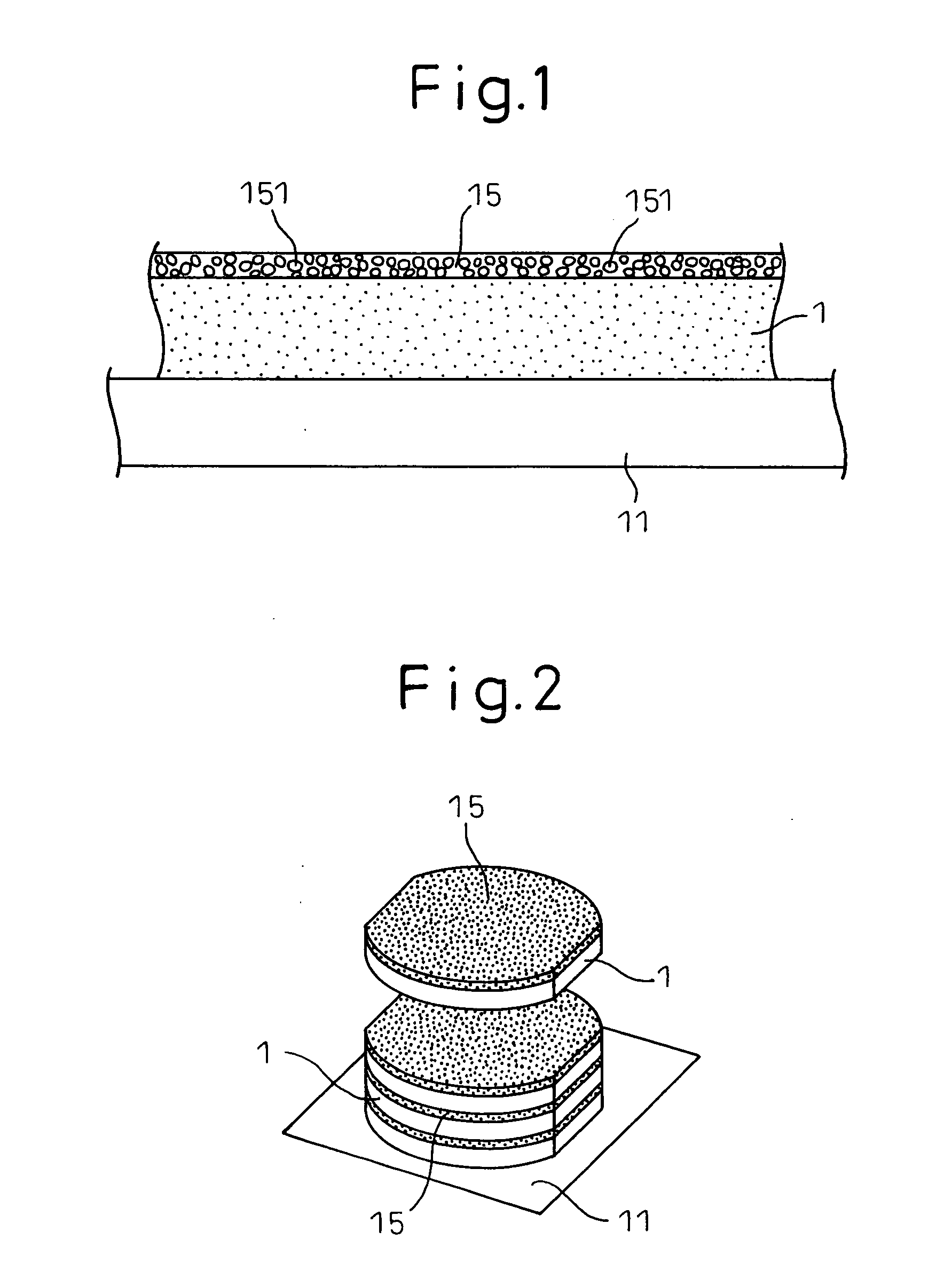
[0121] In this Example, a sheet-making step, a crystallization-promoting layer-forming step and a calcining step are performed. At the sheet-making step, as shown in FIG. 1, a green sheet 1 composed of a piezoelectric material, which forms the polycrystalline substance of the perovskite structure, is made by calcining.

[0122] At the crystallization-promoting layer-forming step, as shown the same Figure, a crystallization-promoting layer 15 comprising crystallization-promoting material particles 151, which allow crystal grains in the polycrystalline substance to grow during calcining, is formed so...

example 2

[0147] This Example is an example of making crystal-oriented ceramics by forming a crystallization-promoting layer on a green sheet containing template particles.

[0148] The crystal-oriented ceramics in this Example are composed of a polycrystalline substance comprising a compound of a perovskite structure {Li0.04(K0.5Na0.5)0.96} (Nb0.86Ta0.1Sb0.04)O3 as a main component, are in the form of a plate, and have the form of a barrel with an area of 52 mm2 (a diameter of 8.5 mm) and a thickness of 80 μm, like in Example 1.

[0149] Details of the method of manufacturing the crystal-oriented ceramics in this Example are described as follows, by using FIGS. 8-15.

[0150] Initially, template particles, which were composed of a perovskite-type compound, and in which a crystal plane, having lattice coherency with a specific crystal plane (orientation plane) of a polycrystalline substance of crystal-oriented ceramics to be made was oriented, and a piezoelectric material were prepared. As the temp...

example 3

[0166] In Example 1 and Example 2, the crystal-oriented ceramics were made by forming the crystallization-promoting layer on the green sheet. This Example is one where crystal-oriented ceramics are made by forming a crystallization-promoting layer between green sheets.

[0167] Concretely, two green sheets with a thickness of 100 μm were made by utilizing slurry, in the same manner as in Example 1.

[0168] Then, particles (with an average diameter of 0.8 μm) composed of MgO2 as crystallization-promoting material particles were dispersed in slurry which had been utilized for the green sheet, and as shown in FIG. 16, a crystallization-promoting layer 15 was formed by applying the slurry at a thickness of about 10μm on one of the green sheets 12. After that, the other green sheet 13 was stacked on the crystallization-promoting layer 15 to make a three-layered green sheet 1. As shown in the same Figure, the crystallization-promoting layer 15 of this Example contains a piezoelectric materia...


PUM

PropertyMeasurementUnit
diameteraaaaaaaaaa
diameteraaaaaaaaaa
temperatureaaaaaaaaaa

Abstract

A method for manufacturing a crystal-oriented ceramic comprising a sheet-making step, a crystallization-promoting layer-forming step and a calcining step is provided. At the sheet-making step, a green sheet 1 is made. At the crystallization-promoting layer-forming step, a crystallization-promoting layer 15 containing crystallization-promoting material particles 151 is formed so as to contact the green sheet 1. At the calcining step, the green sheet is calcined. A method for manufacturing a ceramic laminate comprising a laminate-making step and a calcining step is provided. At the laminate-making step, a laminate is made, where green sheets and electrode-printed layers are stacked. The crystallization-promoting layer, containing the crystallization-promoting material particles, which allow crystal grains in a polycrystalline substance to grow during calcining, is formed so as to contact the green sheet. At the calcining step, the laminate is calcined.

Description

TECHNICAL FIELD [0001] The present invention relates to a method of manufacturing a crystal-oriented ceramic, which are composed of a polycrystalline substance comprising a perovskite structure (ABO3) as the main component, and a method of manufacturing a ceramic laminate in which the crystal-oriented ceramics and internal electrode layers are laminated. BACKGROUND ART [0002] In the past, piezoelectric ceramics have been widely applied in the fields of electronics and mechatronics. Piezoelectric ceramics are subjected to a so-called polarization treatment in which an electric field is applied to ferroelectric ceramics to orient the direction of the ferroelectric domains in a fixed direction. In the case of piezoelectric ceramics, in order to orient spontaneous polarization in a fixed direction by polarization treatment, an isotropic perovskite crystal structure is advantageous, as this allows the direction of spontaneous polarization to be three-dimensional. Consequently, the majori...

Claims


Application Information

Patent Timeline
Patent Type & Authority Applications(United States)
IPC IPC(8): H01L21/00H01L21/302H01L21/461C04B35/00C04B35/64H01L41/083H01L41/187H01L41/22H01L41/297H01L41/39H01L41/43
CPCB32B2315/02C04B35/495C04B35/62218C04B37/008C04B2235/3201C04B2235/3203C04B2235/3206C04B2235/3217C04B2235/3232C04B2235/3251C04B2235/3294C04B2235/3826C04B2235/3873C04B2235/6025C04B2235/768C04B2235/787C04B2237/345H01L41/083H01L41/273H10N30/50H10N30/053
Inventor KADOTANI, SHIGEIWASE, AKIO
Owner DENSO CORP
Why Eureka
Try Eureka