Mask recovering system and mask recovering method

a mask and recovery system technology, applied in the field of mask recovery system and mask recovery method, can solve the problems of difficult to verify that the mask has been reliably crushed based on the image data of the crushed mask, environmental problems, and impose a significant burden on the client in terms of time and cost, so as to reduce the movement of people and the time required to dispose of masks, reduce the effect of manpower and reduce the cost of removal

Inactive Publication Date: 2006-09-14
FUJITSU MICROELECTRONICS LTD
View PDF3 Cites 17 Cited by
  • Summary
  • Abstract
  • Description
  • Claims
  • Application Information

AI Technical Summary

Benefits of technology

[0024] Accordingly, the movement of people and expenditure of time required to dispose of masks can be minimized, and thus the reliability and efficiency of the disposing process can be enhanced.
[0025] According to the mask disposing system and mask disposing method of the present invention, a disposing process and a disposal verifying process for discontinued masks can be performed by a server serving as the core of the system, while minimizing the manpower and saving time.
[0026] Therefore, the present invention significantly contributes to enhance the reliability and efficiency of a mask disposing process in which security protection is important.

Problems solved by technology

When discussing these conventional methods for disposing masks to be securely managed, some problems arise.
That is, in the conventional disposing method (1), it is difficult to verify that the mask has been reliably crushed based on the image data of the crushed mask.
Further, the crushed mask is abandoned with a Cr film or the like being attached thereto, which causes an environmental problem.
Further, the returned mask needs to be abandoned by the client, which is inconvenient.
In the conventional disposing methods (3) and (4), the client needs to come to the site of disposal every time a mask is disposed of, which imposes a significant burden on the client in terms of time and cost.
On the other hand, a semiconductor device manufacturer stores many masks, and thus storing discontinued masks leads to wastes of load and cost of a storage place and management.

Method used


Image

  • Mask recovering system and mask recovering method
  • Mask recovering system and mask recovering method
  • Mask recovering system and mask recovering method

Examples


first embodiment

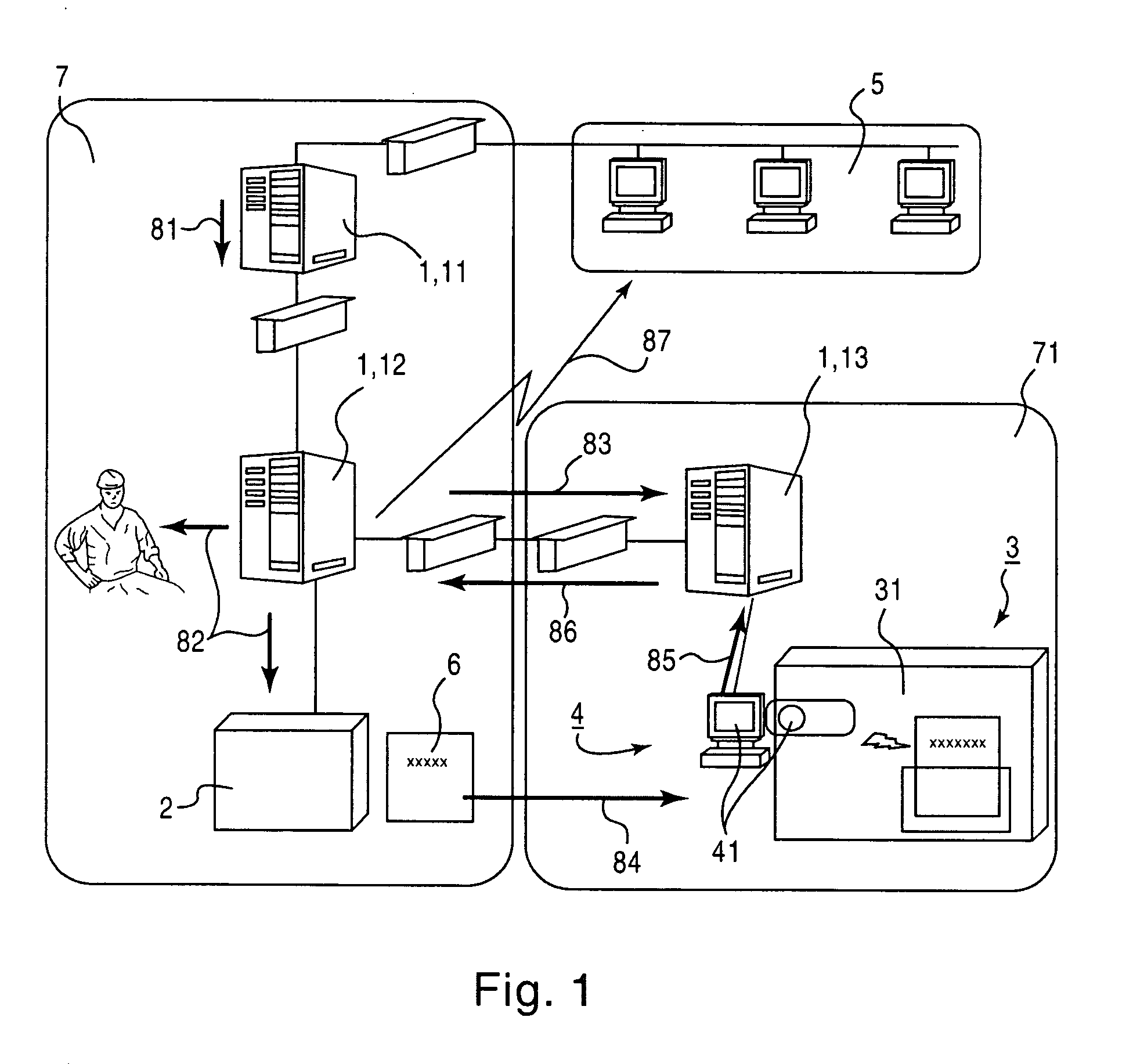
[0056] In FIG. 1, three servers as the servers 1 connect to each other through the network. The first server 11 and the second server 12 are placed in a company A, whereas the third server 13 is placed in a company B. In the example shown here, the company A is a semiconductor device manufacturer 7 and the company B is a mask manufacturer 71, which has the disposing unit 3 and the disposal verifying unit 4.

[0057] When a client accesses the first server 11 of the company A from the client terminal 5 in order to request disposal of the mask 6, the disposal request is transmitted to the second server 12 along the arrow 81 and is registered therein. Then, the second server 12 transmits the disposal request to a person involved and the storage cabinet 2 along the arrows 82 and to the third server 13 placed in the company B along the arrow 83. The storage cabinet 2 takes the specified mask 6 out of storage and transmits the mask 6 to the company B along the arrow 84.

[0058] The company B...

second embodiment

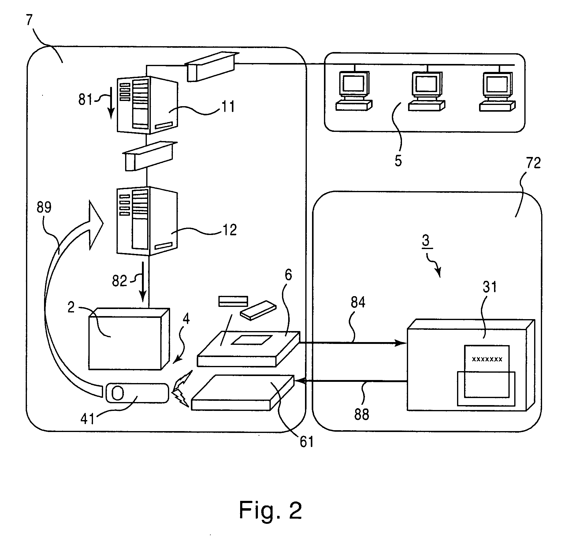
[0114] In FIG. 2, two servers connect to each other through a network. The first server 11 and the second server 12 are placed in the company A, which is also provided with the disposal verifying unit 4. The company B includes the disposing unit 3. That is, in the example shown here, the company A is the semiconductor device manufacturer 7 and the company B is the mask disposing company 72.

[0115] If the client accesses the first server 11 of the company A from the client terminal 5 in order to request disposal of the mask 6 to be discontinued, the request is registered in the second server 12. At this time, a character that is arbitrarily specified by the client is registered together. In the storage cabinet 2, the specified mask 6 is taken out therefrom. The disposal verifying unit 4 inscribes the character specified by the client on the mask 6 near a mask ID by using laser. Then, the disposal verifying device 41 such as a video camera takes an image of the mask 6 with the charact...

third embodiment

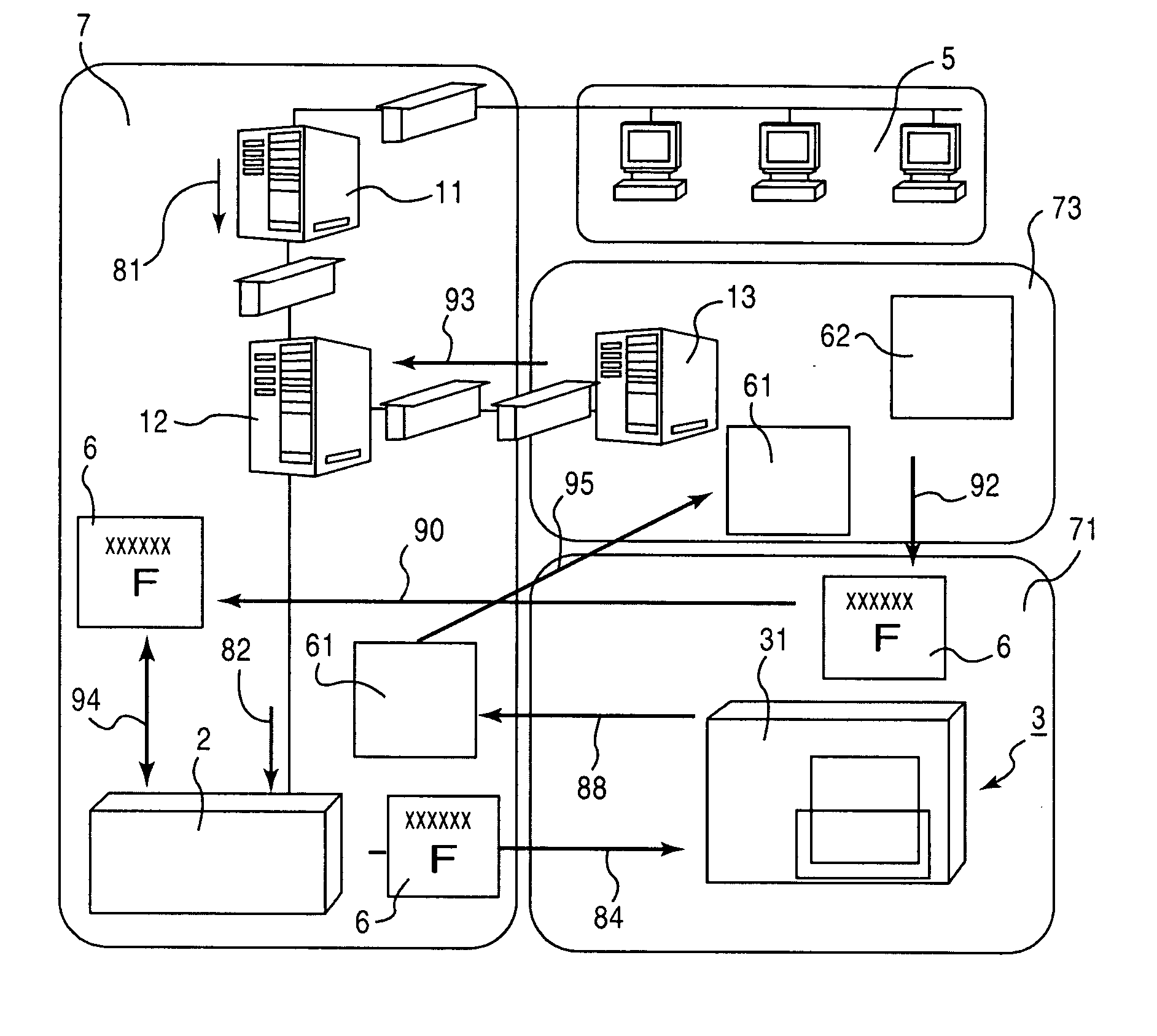
[0160] In FIG. 3, three servers connect to each other through a network. The first server 11 and the second server 12 are placed in the company A, whereas the third server 13 is placed in the company B together with the disposing unit 3 and the disposal verifying unit 4. In the example shown here, the company A is the semiconductor device manufacturer 7 and the company B is the mask manufacturer 71. The company B supplies masks 6 to the company A along the arrow 90.

[0161] When the company B purchases substrates for the masks 6, the company B purchases virgin substrates 62 with serial numbers and manages them. When the masks 6 are supplied from the company B, the company A registers the serial numbers and mask IDs of the respective masks 6 in the second server 12 so that a client can browse them, and stores the masks 6 in the storage cabinet 2 along the arrow 91.

[0162] When the client accesses the first server 11 of the company A through the client terminal 5 and requests disposal ...


PUM

PropertyMeasurementUnit
roughnessaaaaaaaaaa
flatnessaaaaaaaaaa
thicknessaaaaaaaaaa

Abstract

A mask disposing system is configured in the following manner. A server receives a request to dispose of a mask to be discontinued from a client terminal through a network, provides instructions to take the mask out to a storage cabinet, provides instructions to dispose of the mask to a disposing unit, and provides a disposal verifying information from a disposal verifying unit to the client terminal. The storage cabinet stores the mask. The disposing unit disposes of the mask by crushing the mask pattern on the mask so that the mask pattern becomes unreadable. The disposal verifying unit verifies that the mask has been crushed and disposed of.

Description

CROSS-REFERENCE TO RELATED APPLICATIONS [0001] This applications is based on, and claims prioryty to, Japanese patent application 2005-272254, filed Sep. 20, 2005, in Japan, and which is incorporated herein by reference. [0002] This applications is based on, and claims prioryty to, Japanese patent application 2005-71324, filed March 14, in Japan, and which is incorporated herein by reference. BACKGROUND OF THE INVENTION [0003] 1. Field of the Invention [0004] The present invention relates to management of photomasks for exposure (hereinafter referred to as masks) used to manufacture semiconductor devices, particularly to a safe method of disposing masks for in-house use and masks used in entrusted business in which the security is strictly managed. [0005] 2. Description of the Related Art [0006] A semiconductor device manufacturing plant that performs exposure using masks and a plurality of departments: a department of designing the masks and a department of ordering the masks, rela...

Claims


Application Information

Patent Timeline
Patent Type & Authority Applications(United States)
IPC IPC(8): G06F17/30G06F7/00G03F1/68H01L21/027
CPCG03F7/70525G03F7/70741
Inventor SAKAMOTO, KAZUTAKAMORIO, MASARU
Owner FUJITSU MICROELECTRONICS LTD
Why Eureka
Try Eureka